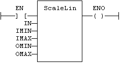
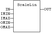
IN : REAL Real value
IMIN : REAL Minimum input value
IMAX : REAL Maximum input value
OMIN : REAL Minimum output value
OMAX : REAL Maximum output value
OUT : REAL Result: OMIN + IN * (OMAX - OMIN) / (IMAX - IMIN)
| Inputs | OUT |
|---|---|
|
IMIN >=IMAX |
= IN |
|
IN < IMIN |
= IMIN |
|
IN >IMAX |
= IMAX |
|
other |
= OMIN + IN * (OMAX - OMIN) / (IMAX - IMIN) |
OUT := ScaleLin (IN, IMIN, IMAX, OMIN, OMAX);
(* The function is executed only if EN is TRUE *)
(* ENO keeps the same value as EN *)
Op1: LD"Ladder diagram"
Ladder logic is a method of drawing electrical logic schematics. It is now a very popular graphical language for programming Programmable Logic Controllers (PLCs). It was originally invented to describe logic made from relays. The name is based on the observation that programs in this language resemble ladders, with two vertical "rails" and a series of horizontal "rungs" between them IN
ScaleLin IMAX, IMIN, OMAX, OMIN
ST OUT
|
Stay Connected with Kollmorgen       
|
Copyright © 2015 Kollmorgen™ |

|