 Velocity LoopVelocity Loop
The velocity loop is active when the drive operates in velocity mode (DRV.OPMODE = 1) or position mode (DRV.OPMODE = 2). The parameters that govern the velocity loop are shown in the Velocity Loop view. This view is only available while in Operation Mode 1 or 2. The various types of tuning for the drive adjust these parameters automatically, so you normally do not need to adjust the velocity loop parameters in the velocity loop screen.
The velocity view includes an active block diagram. If you click on a block in the diagram, the appropriate tab opens below.
Ramp limiter . The ramp limiter consists of the acceleration limits of the drive. These acceleration limits override both motion task and electronic gearing acceleration limits, so they must be set higher than the highest required motion task acceleration or gearing acceleration value. These acceleration and deceleration limits are also shown in the Service Motion view and the Limits view (DRV.ACC and DRV.DEC ).
Velocity clamp. The velocity clamp affects the maximum speed of the drive when the command source is service (DRV.CMDSOURCE = 0). This speed limit affects motion commanded in service motion and in motion tasks. These limits are also found in the limit screen on WorkBench. (VL.LIMITP and VL.LIMITN )
AR1, AR2, AR3, AR4: These values are the independent bilinear quadratic (bi-quad) filters inside the drive. AR1 and AR2 are in the forward path and AR3 and AR4 are in the feedback path. These bi-quad filters can each be configured in five different modes.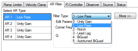
0–Unity Gain. The filter is off, and it will not affect the loop.
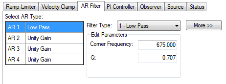
1–Low Pass. In modes 1, 2, and 3, the bi-quad filter is configured for each respective type of filtering. The Edit Parameters field is used to set up the filter. The actual bi-quad filter values are shown to the left:
2–Notch
3–Lead Lag
4–Bi-quad . A manually configured Bi-quad filter. This is an advanced tuning function.
5–Autotuned Biquad . When the PST sets a filter after the PST process is complete, the values are input into the Bi-Quad filter and are shown as read only values.
By default, a PI loop with a low-pass filter (AR3) is set in the drive.
The default value for the low-pass filter is 400 Hz. The low-pass filter is important for disturbance rejection, and it also reduces the audible noise of the system.
Slider tuning (see Slider Tuning) uses the slider control to adjust the proportional gain and integral gain values of the velocity loop based on the desired bandwidthIn computer networking, bandwidth often refers to a data rate measured in bits/s, for example, network throughput. The reason for the connection of data rate with the term bandwidth is that the limit to the data rate of a physical communication link is related to its bandwidth in hertz. If you adjust the bandwidth using the slider tuner and then return to the velocity loop screen, you will see different values inside the proportional gain and integral gain fields. No adjustment is made to the filters automatically by using the slider tuner. Only the proportional and integral terms are adjusted.
Filters in the AKD all exist as digital biquad filters in the servo loops. Lowpass, LeadLag, and Resonator filters are derived by the following equations. WorkBench handles all the math involved for the user. Enter the values in the fields for the type of filter desired.
Numerator Frequency = 5000
Numerator Q = Sqrt(2)/2 (this is 0.707)
Denominator Frequency = F
Denominator Q = Sqrt(2)/2 (this is 0.707)
Numerator Frequency = F * 10^(-G/80)
Numerator Q = Sqrt(2)/2 (this is 0.707)
Denominator Frequency = F * 10^(G/80)
Denominator Q = Sqrt(2)/2 (this is 0.707)
Numerator Frequency = F
Numerator Q = 10^(-G/40) * Q
Denominator Frequency = F
Denominator Q = 10^(G/40) * Q
Related Parameters
VL Parameters | DRV.ACC | DRV.CMDSOURCE | DRV.DEC | DRV.OPMODE
Related Topics
Limits | Service Motion | Tuning Your System | Motion Tasks (pg 1)
|
Stay Connected with Kollmorgen       
|
Copyright © 2015 Kollmorgen™ |

|