 FB_PWDutyOutput FB_PWDutyOutput
The PulseWhen the step gets activated, the action is activated for a single execution, and possibly once again when the step is deactivated Width Duty Cycle function block accepts an input value between the minimum and maximum input range and converts this to a duty cycle percentage. The output is then cycled on and off over the period of the duty cycle at the duty cycle percentage. If it is desired to have the output ON time range from 0 to the duty cycle period, the minimum should be set to zero and the maximum to the duty cycle period. If the calculated duty cycle based on the input and range values is less than the minimum ON time (MinTime), the output will not come on. If the calculated duty cycle is between or equal to the range values the output is cycled by the duty cycle. If the calculated duty cycle is greater than the maximum ON time (MaxTime) the output will remain on.
The following figure shows the function block I/O
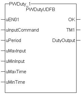
Figure 11-189: Pulse Width Duty Cycle
| uEN01 | Description | EnableEnable signal for the drive, Hardware-Enable with 24V signal to X8, Software-Enable command by setup Software, fieldbus or permanently set. Both are required for enabling the drive. for the block |
| Data type | BOOL | |
| Range | [0 , 1] | |
| Unit | n/a | |
| Default | — | |
| uInputCommand | Description | Signal Input (sometimes the output of a PID"Proportional-Integral-Derivative" A PID controller is a generic control-loop feedback mechanism widely used in industrial control systems. An "error" occurs when an event or a disturbance triggers off a change in the process variable. A PID controller attempts to correct the error between a measured process variable and a desired setpoint by calculating and then outputting a corrective action that can adjust the process accordingly block). |
| Data type | REAL | |
| Range | [0 to -- ] | |
| Unit | n/a | |
| Default | — | |
| uPeriod | Description | Period of the duty cycle |
| Data type |
TIME |
|
| Range | [0 , -- ] | |
| Unit | n/a | |
| Default | — | |
| uMaxInput | Description | uInputCommand at or above this number that sets DutyOutput =1 |
| Data type | REAL | |
| Range | uMinInput to -- | |
| Unit | n/a | |
| Default | — | |
| uMinInput | Description | uInputCommand at or below this number set DutyOutput = 0 |
| Data type | REAL | |
| Range | 0 to uMaxInput | |
| Unit | n/a | |
| Default | — | |
| uMaxTime | Description | Maximum on time for the Output |
| Data type |
TIME |
|
| Range | uMinTime to uPeriod | |
| Unit | n/a | |
| Default | — | |
| uMinTime | Description | Minimum on-time for the PW Duty Output |
| Data type |
TIME |
|
| Range | 0 to uMaxTime | |
| Unit | n/a | |
| Default | — |
| OK | Description |
Fucnction block is OK. |
| Data type | BOOL | |
| Range | [0 , 1] | |
| TM1 | Description | On-time of the Output |
| Data type |
TIME |
|
| Range | 0 to uPeriod | |
| DutyOutput | Description | PW signal ( switching between 0 and 1) |
| Data type | BOOL | |
| Range | [0 , 1] |
Flash a warning light for operators.
IF (uInputCommand - uMinInput) < 0 then     //If Command less than MinInput turn out put off
   DutyOutput := 0;
ELSIF (uInputCommand - uMaxInput) > 0 then     //If Command greater than MaxInput turn out put on
   DutyOutput := 1;
ELSE
   DutyCycle := (uInputCommand - uMinInput)/(uMaxInput - uMinInput);     //Calculate Duty Cycle
   ONTimeFromInput := DutyCycle * any_to_REAL(uPeriod) ;     //Calculate Ontime

   IF  any_to_TIME(ONTimeFromInput)  < uMinTime then
      DutyOutput := 0;
   ELSIF any_to_TIME(ONTimeFromInput) > uMaxTime then
      DutyOutput := 1;
   ELSE
      TM1 := any_to_TIME(ONTimeFromInput) ;
      TM0 :=  uPERIOD - TM1;     //Calculate offtime
      DutyOutput := Inst_blinkA( 1 , TM0 , TM1 );     //Use BlinkA function to set PW output
   END_IF ;
END_IF ;
|
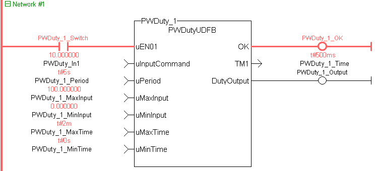
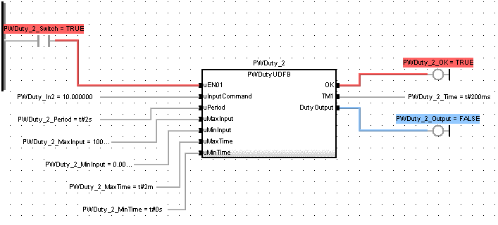
Inst_FB_PWDutyOutput( PWDuty_3_Switch, PWDuty_In3, PWDuty_3_Period, PWDuty_3_MaxInput, PWDuty_3_MinInput, PWDuty_3_MaxTime, PWDuty_3_MinTime); PWDuty_3_OK:=Inst_FB_PWDutyOutput.OK; PWDuty_3_Time:=Inst_FB_PWDutyOutput.TM1; PWDuty_3_Output:=Inst_FB_PWDutyOutput.DutyOutput;
|
|
Stay Connected with Kollmorgen       
|
Copyright © 2015 Kollmorgen™ |

|
 [Top]
[Top]