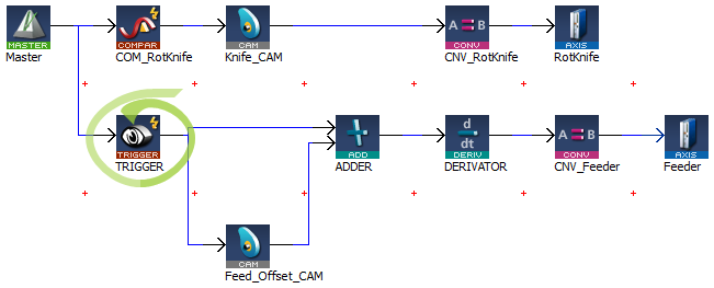
A Pipe Network Trigger block can be used for registration applications to capture a pipe position based on a timestampA timestamp is a sequence of characters, denoting the date and/or time at which a certain event occurred which is set when a drive's fast inputThe inputs are taken into account at each cycle depending on the system periodicity (for example each millisecond). Under certain circumstances this can be insufficient when more accuracy is needed, or if a quick response is required from the system. To fill the gap, a drive may have some Fast Input connections (generally one or two). When an event happens that triggers a Fast Input (e.g. when a sensor sends a rising edge), the detection of a signal occurs faster (which can be 1000 times more accurate than the system periodicity). Then the timestamp associated with this input can be provided to the IPC to take corrective action changes state. A Trigger block is placed in the Pipe Network precisely where the pipe position needs to be captured.
Figure 11-22: Example of using a Pipe Network Trigger block for position capture.
The Pipe Network motion engine captures the pipe position by using the timestamp received from the drive and interpolating two consecutive pipe position updates. The timestamp will have a delay getting into the pipe network from the drive (typically 2 cycles) due to sensorA sensor is a type of transducer that converts one type of energy into another for various purposes including measurement or information transfer delay and the signal processing through the EtherCATEtherCAT is an open, high-performance Ethernet-based fieldbus system. The development goal of EtherCAT was to apply Ethernet to automation applications which require short data update times (also called cycle times) with low communication jitter (for synchronization purposes) and low hardware costs network .
Corrected timestamp: = Fast input timestamp - DelayCompensation
To account for this delay, MLTrigWriteDelay provides delay compensation to the pipe position returned in MLTrigReadPos based on the expected delay.
The Trigger block is first configured by clicking on the block in a pipe network and setting the following parameters.
Figure 11-23: Configuration of the Trigger block
After configuring the Trigger block, the order of calls to its motion library functions is as follows:
You have to correct the position by taking into account the delay due to the number of cycles needed to read the timestamp of the Fast Input. You can use MLTrigWriteDelay to address this issue.
After the Trigger block pipe position is determined and calculations are made in the Registration program, a corrective move is typically done using a Cam Pipe Network block for precision motion controlMotion control is a sub-field of automation, in which the position and/or velocity of machines are controlled using some type of device such as a hydraulic pump, linear actuator, or an electric motor, generally a servo. Motion control is an important part of robotics and CNC machine tools; however, it is more complex than in the use of specialized machines, where the kinematics is usually simpler. The latter is often called General Motion Control (GMC). Motion control is widely used in the packaging, printing, textile and assembly industries.
|
Stay Connected with Kollmorgen       
|
Copyright © 2015 Kollmorgen™ |

|