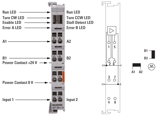
General Specification
The Bus Terminal is intended for the direct connection of different small stepper motors. The slimline PWM output stages for two motor coils are located in the Bus Terminal together with two inputs for limit switches. The terminal can be adjusted to the motor and the application by changing just a few parameters. 64-fold micro-stepping ensures particularly quiet and precise motor operation. In many applications, integrated zero-speed monitoring makes an encoder system or limit switch unnecessary.
Electrical and Mechanical Specification

|
Electrical and Mechanical Specification
|
AKT-SM-L15-000
|
|---|---|
|
Number of outputs
|
1 Stepper Motor, 2 phases
|
|
Number of inputs
|
2
|
|
Output current
|
2 x 1 A, 2 x 1.5 A peak current, overload- and short-circuit-proof
|
|
Maximum step frequency
|
125,000 steps/s
|
|
Step pattern
|
full step, half step, up to 64-fold micro stepping
|
|
Current controller frequency
|
approx. 25 kHz
|
|
Diagnostics LED
|
error phase A and B, loss of step/stagnation, power, enable
|
|
Resolution
|
approx. 5,000 positions in typ. applications (per revolution)
|
|
Power supply
|
8...24 V DC (for output stage over power contacts)
|
|
Electrical isolation
|
500 Vrms (Standard Bus/signal voltage)
|
|
Current consump. from Standard Bus
|
typ. 60 mA
|
|
Bit width in the process image
|
input: n x 2 x 16 bit data, 2 x 16 bit control/status
|
|
Weight
|
50 g
|
|
Operating/storage temperature
|
0…+55 °C/-25…+85 °C
|
|
Relative humidity
|
95 %, no condensation
|
|
Vibration / shock resistance
|
conforms to EN 60068-2-6/EN 60068-2-27/29
|
|
EMC immunity/emission
|
conforms to EN 61000-6-2/EN 61000-6-4
|
|
Protect. class / installation pos.
|
IP 20/variable
|
|
Pluggable wiring
|
For all Bus terminals
|


