State Machine
The device control of the AKD2G can be used to carry out all the motion functions in the corresponding modes. The control of the AKD2G is implemented through a mode-dependent state machine. The state machine is controlled through 6040h: Control Word (DS402). The mode setting is made through 6060h: Modes of Operation (DS402). The states of the state machine are indicated in 6041h: Status Word (DS402). There are separate state machines for each axis.
-
- The fieldbus state machine will control the axis as long as AXIS#.CMDSOURCE is equal to Fieldbus
 A Fieldbus is an industrial network system for real-time distributed control (e.g. CAN or Profibus). It is a way of connecting instruments in a plant design. In order to enable the axis via WorkBench, AXIS#.CMDSOURCE should be changed to Service mode.
State Machine (DS402)
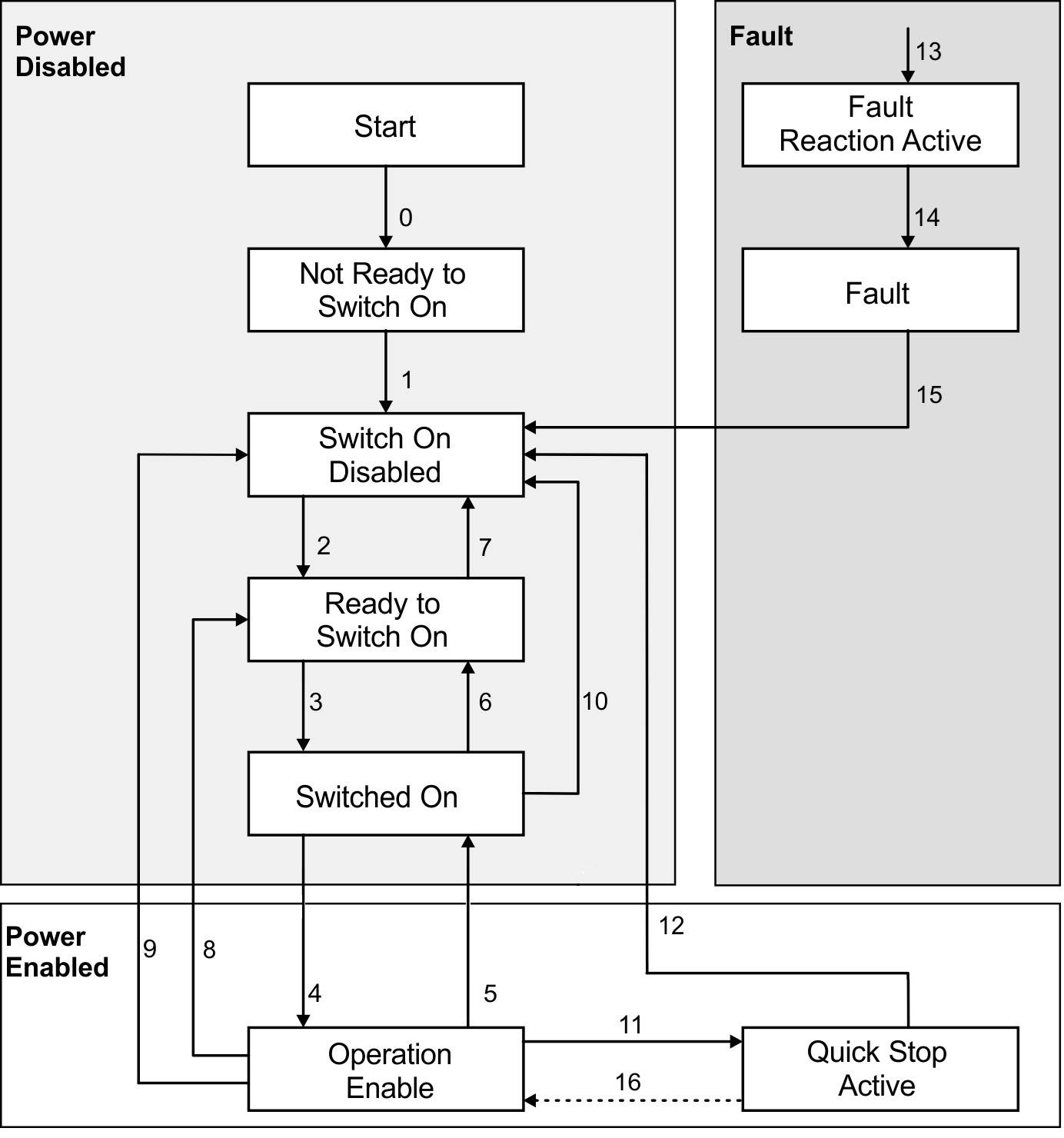
States of the State Machine
| State | Description |
|---|---|
| Not Ready for Switch On | Axis is not ready to switch on, initialization has not completed. |
| Switch On Disable | Axis is ready to switch on, parameters can be transferred, the bus voltage can be switched on, motion functions cannot be carried out yet. |
| Ready to Switch On | Bus voltage may be switched on, parameters can be transferred, motion functions cannot be carried out yet. |
| Switched On | Bus voltage must be switched on, parameters can be transferred, motion functions cannot be carried out yet. |
| Operation Enable | No fault present, output stage and motion functions are enabled. |
| Quick Stop Active | Drive has been stopped with the emergency ramp, output stage is enabled, motion functions are not enabled. |
| Fault Reaction Active | A fault has occurred, the drive is in process of stopping with the quickstop ramp. |
| Fault | A fault is active, the drive has been stopped and disabled. |
Transitions of the state machine
The state transitions are affected by internal events (ex: switching off the bus voltage, WorkBench enable/disable) and by the flags in the control word (bits 0,1,2,3,7).
| Transition | Event | Action |
|---|---|---|
| 0 | Reset | Initialization |
| 1 | Initialization completed successfully. The axis is ready to operate. | None |
| 2 | Bit 1 Disable Voltage and Bit 2 Quick Stop are set in the control word (Shutdown command). Bus voltage may be present. | None |
| 3 | Bit 0 is also set (Switch On) and bus voltage is present | None |
| 4 | Bit 3 is also set (Enable Operation) | Torque |
| 5 | Bit 3 is canceled (Disable Operation) | Output stage is disabled. No torque |
| 6 | Bit 0 is canceled (Shutdown) | None |
| 7 | Bits 1 and 2 are canceled (Quick Stop/Disable Voltage) | None |
| 8 | Bit 0 is canceled (Shutdown) | Output stage is disabled. No torque applied to motor. |
| 9 | Bit 1 is canceled (Disable Voltage) | Output stage is disabled. No torque applied to motor. |
| 10 | Bits 1 and 2 are canceled (Quick Stop/Disable Voltage) | Output stage is disabled. No torque applied to motor. |
| 11 | Bit 2 is canceled (Quick Stop) | Drive is stopped with the emergency braking ramp. The output stage remains enabled. Setpoints are canceled (motion block number, digital setpoint |
| 12 | Bit 1 is canceled (Disable Voltage) | Output stage is disabled. No torque applied to motor. |
| 13 | Fault reaction active | Execute appropriate fault reaction |
| 14 | Fault reaction is completed | Drive function is disabled. The power section may be switched off. |
| 15 | "Fault Reset" command received from host | A reset of the fault condition is carried out if no fault exists currently on the drive. After leaving the state Fault the Bit7 'Reset Fault' of the control word must be cleared by the host. |


