Circular and Linear Interpolation w/ PLCopen Motion Engine
Introduction
This application example details sample code for a 3 axis system:
- X, Y Axis - Horizontal Axes
- Z axis - Vertical Axis
- FFLD (Free Form Ladder Diagram) , SFC
 "Sequential function chart"
It can be used to program processes that can be split into steps.
The main components of SFC are:
- Steps with associated actions
- Transitions with associated logic conditions
- Directed links between steps and transitions, and ST"Structured text"
A high-level language that is block structured and syntactically resembles Pascal languages were used.
"Sequential function chart"
It can be used to program processes that can be split into steps.
The main components of SFC are:
- Steps with associated actions
- Transitions with associated logic conditions
- Directed links between steps and transitions, and ST"Structured text"
A high-level language that is block structured and syntactically resembles Pascal languages were used. - PLCopenA vendor -and product- independent worldwide association active in Industrial Control and aiming at standardizing PLC file formats based on XML Motion Engine was used.
- Motions: Group motion setup and operation including homing, 2 axis linear interpolation, and circular interpolation, motion blending and transition between coordinated motion moves, and stop and restart coordinated motion along the path.
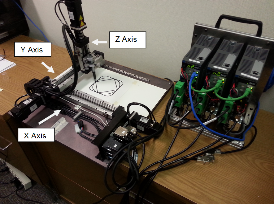
- Hardware: An X, Y, and Z motion table was used to demonstrate 2 axis coordinated motion capabilities of the KAS motion system. Each axis is equipped with hardware limit switches for homing and position initialization. A traditional circle, diamond, square figures are made using a pen lowered to paper.
- Control Panel: Created inside the KAS IDE"Integrated development environment"
An integrated development environment is a type of computer software that assists computer programmers in developing software.
IDEs normally consist of a source code editor, a compiler and/or interpreter, build-automation tools, and a debugger for use during development and operation.
- Project file: Sample KAS Coordinated Motion Application CDS.kas. For zip file with sample code visit: http://www.kollmorgen.com/en-us/products/machine-controls/automation-platform/kollmorgen-automation-suite/kollmorgen-automation-suite#tab8
PLC Program Code
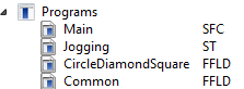
The application code provided with this application module is contained in four programs (that can be exported then imported into a project):
| Program Name | Function |
Language |
|---|---|---|
| Main | Initialize the axis, the axis group, and motion | Sequential Function Chart(SFC) with Structured Text (ST) |
| Jogging | Jog the axes | Structured Text (ST) |
| CircleDiamondSquare | Perform homing and the circle, diamond, square motion | FFLD (Free Form Ladder Diagram) |
| Common | Common application functionality: Error Reset, Power Axis On/Off, Enable Group Motion, Read Axis Status, Read Axis Positions, Read Axis Group Positions | FFLD (Free Form Ladder Diagram) |
The key function blocks and Kollmorgen UDFBs used in the application:
| Name | Function | Program |
|---|---|---|
| MC_InitAxesGrp | Home the axis | Main |
| MC_AddAxisToGrp | Set a motor/load position after homing | Main |
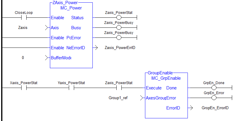
| IMC_GrpEnable | Enable the group motion | Common |
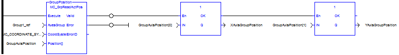
| MC_GrpReadActPos | Read group position | Common |
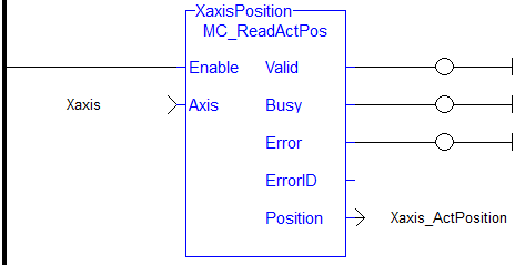
| MC_ReadActPos | Read individual axis positions | Common |
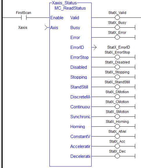
| MC_ReadStatus | Read axis status | Common |
| MC_Power | Power an axis | Common |
| MC_MoveRelative | Make a relative move | CircleDiamonSquare |
| MC_SetPosition | Establish axis position after homing | CircleDiamonSquare |
| MC_SetHomePosition | Establish home position for the axis group | CircleDiamonSquare |
| MC_MoveLinAbs | Move 2 axis (x, y) linear interpolation move | CircleDiamonSquare |
| MC_MoveCircAbs | Move 2 axis (x, y) circular interpolation move | CircleDiamonSquare |
Main Program
The main program consists of 2 steps: Setup and IDLE:
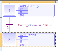
In the Setup step:
- The motion objects are created
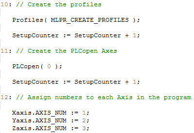
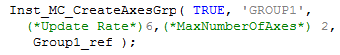
- The Axis Group is created
- The Axis Group is initialized

- Axes are added to the group


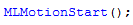
- Motion engine is started
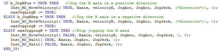
Jogging Program
The Jogging Program allows motor jogging in either direction. The following is the code for the X axis. The Y and Z axis are similar:
CircleDiamonSquare Program
The CircleDiamondSquare program performs 2 axis coordinated motion. Key parts of the program are as follows:
- Network 2: Define default CM (coordinated motion) absolute positions, CM transition and CM move parameters. This is a large section that defines the starting parameters in the application. This network is executed once on program startup. Values can be change using the control panel ( CP_CircleDiamondSquare).
-
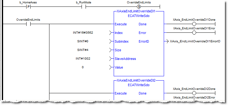
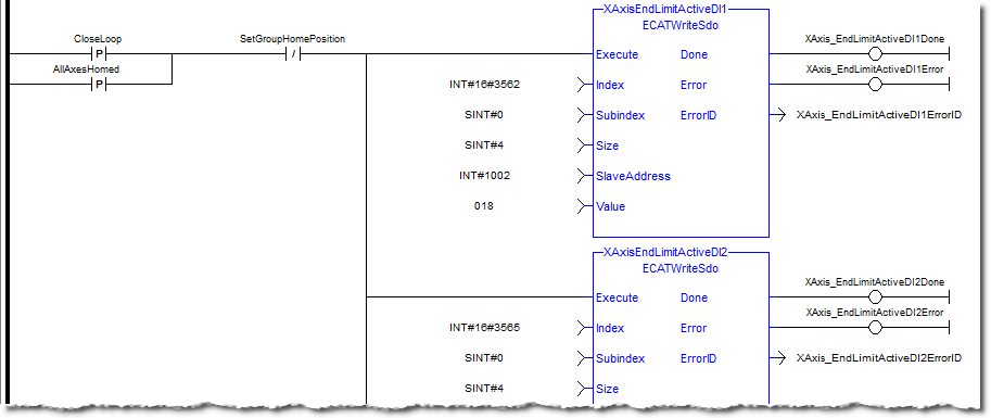
2. Network 3: Disable limit switches before homing:
-
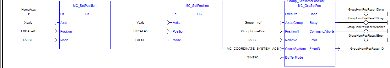
Network 4: Reset both single axis and CM axes command and actual positions to zero before any homing sequence. This is necessary so the summed super imposed axis positions are 0 and will not affect single axis motion.
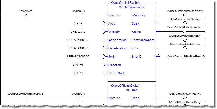
- Network 5: Home axes to limit switches after operator input. If the axis is on the limit switch back off first. Move to the axis 0 and set the position to 0.
-
Network 6: End limits and home switches are common for each axis, therefore the re-enable of end limits after the axis home sequence is completed is performed:
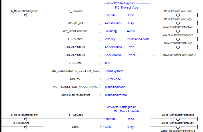
- Network 7: Move X and Y axis to starting point. Move Z to starting point
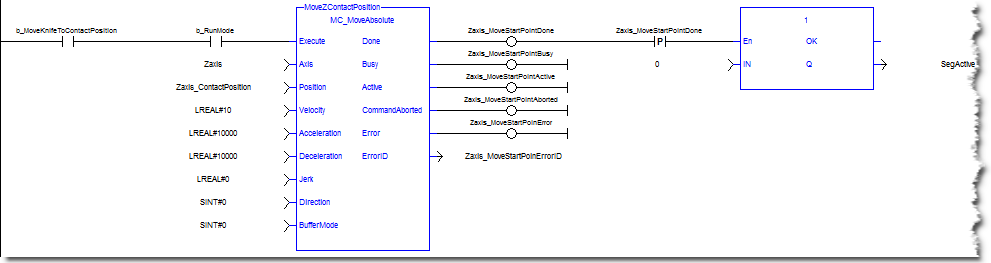
- Network 8: Lower knife to contact point
-
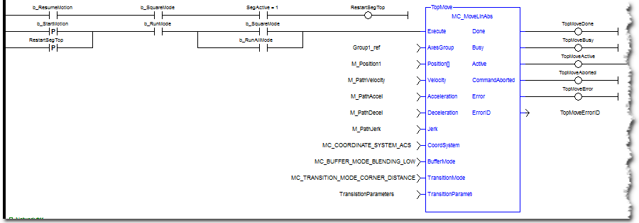
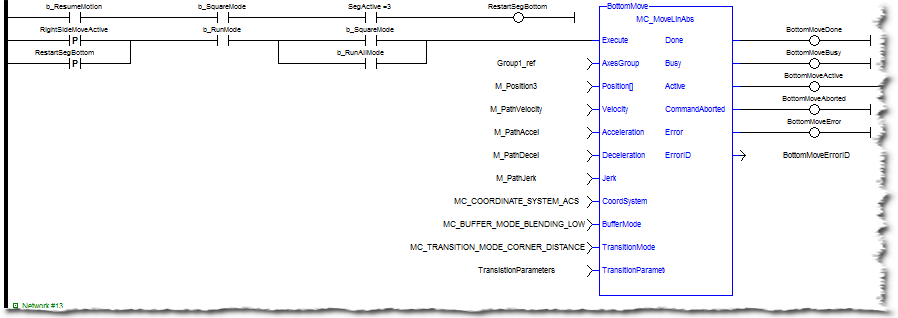
Networks 10 to 13: Make Square CM move. The starting position is the center or half way distance point of the top segment. This is required so the final corner of the square will transition with a radius. If the starting point was at the corner then the last segment would not be a radius. This starting position is also the ending point for the square. Restart the segment move if it has been halted while in motion.
-
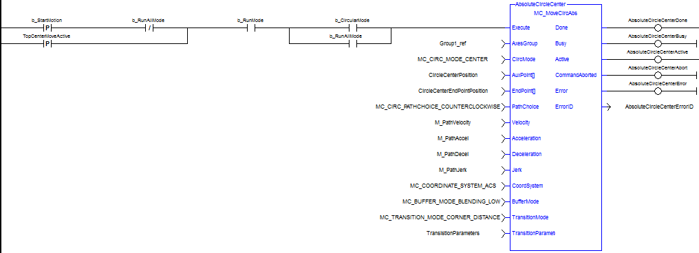
Network 15: Make circle move. The default circle center XY positions are based on the square center point.
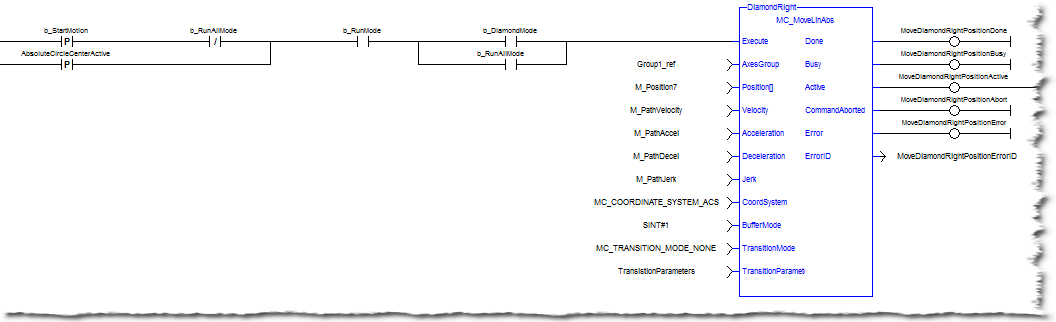
- Network 19: Make diamond move
Common Program
The Common Program performs standard functions used in many applications.
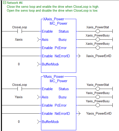
-
This code powers up the axis and the axis group:
- The following outputs the present motion status of each axis (only X axis shown):
-
The following outputs actual positions of each axis and the group (only X axis shown):
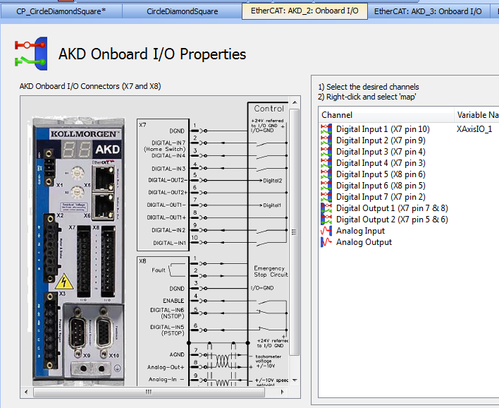
Key Drive I/O
For each of the X, Y, and Z axes an input on the drive (on connector X7) was mapped for the axis homing functionality. The following shows the X axis mapping:
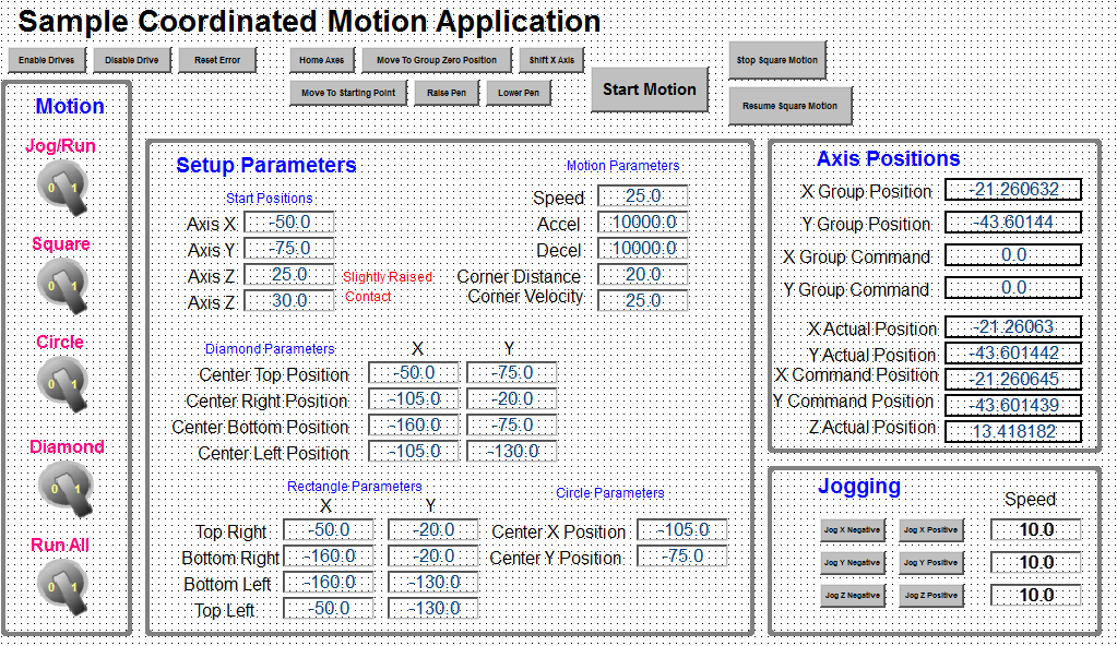
Control Panel
A Control Panel has been created to run the program:
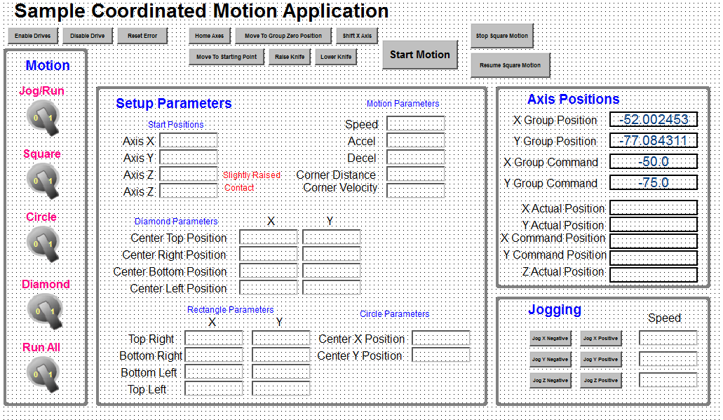
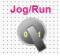
Motion
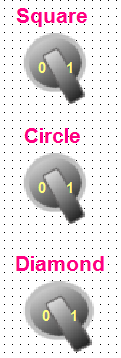
These bottons determine what motion is run. To jog the motors, select Jog in the Jog/Run bottom. To make a circle, diamond, square shape select Run and then the switch for the appropaite figure type or select the run all button to run all 3 figures.
Setup Parameters
These parameters setup the circle, diamond, or square motions.
Axis Position
Axis and Group Positions are both shown.
-
-
There can be a different coordinate system for each
Jogging
These controls are for the jogging motion.
Top Buttons
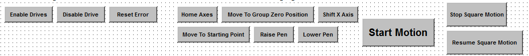
- To make a circle, diamond, and/or square motion:
- Enable the drives:

- Select run:
- Home axis:

- Move Axis to starting position:
- Lower the pen:

- Select motion type:
- Enable the drives:
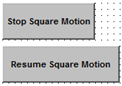
- Code has been added to the program to stop and restart along the path during the square motion move: