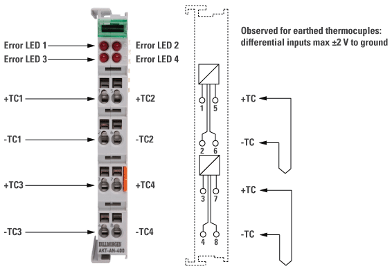
General Specification
The analog input terminal allows four thermocouples to be connected directly. The Bus Terminal’s circuitry can operate thermocouple sensors using the 2-wire technique. Linearization over the full temperature range, which can be selected freely, is realized with the aid of a microprocessor. The error LEDs indicate a broken wire. Compensation for the cold junction is made through an internal temperature measurement at the terminals. Can also be used for mV measurement.
Electrical and Mechanical Specification

|
Electrical and Mechanical Specification
|
AKT-AN-400-000
|
|---|---|
|
Number of inputs
|
4
|
|
Power supply
|
via the Standard Bus
|
|
types J, K, L, B, E, N, R, S, T, U (default setting type K), mV measurement
|
|
|
Connection Method
|
2-wire
|
|
Temperature range
|
in the range defined in each case for the sensor (default setting: type K; -100…+1,370 °C)
|
|
Resolution
|
0.1 °C per digit
|
|
Conversion time
|
~ 250 ms
|
|
Wiring fail indication
|
yes
|
|
Measuring error
|
< ±0.5 % (relative to full scale value)
|
|
Electrical isolation
|
500 Vrms (Standard Bus/signal voltage)
|
|
Current consumption from Standard Bus
|
typ. 75 mA
|
|
Bit width in the process image
|
input: 4 x 16 bit data (4 x 8 bit control/status optional)
|
|
Configuration
|
no address setting, configuration via Bus Coupler or controller
|
|
Weight
|
75 g
|
|
Operating/storage temperature
|
0 C ... +55 °C /-25 °C... +85 °C
|
|
Relative humidity
|
95 %, no condensation
|
|
Vibration / shock resistance
|
conforms to EN 60068-2-6 / EN 60068-2-27/ 29
|
|
EMC immunity/emission
|
conforms to EN 61000-6-2 / EN 61000-6-4
|
|
Protect. class / installation pos.
|
IP 20 / variable
|
-
-
24-volt power is not passed through AKT-AN-200-000 and AKT-AN-400-000 thermocouple modules. To get 24VDC power to devices that need it (such as an AKT_AT-410-000 Output module) there are two possible solutions.
- Place the module requiring 24VDC before the thermocouple module.
- Add a power feed module (AKT-PS-024-000 or AKT-PSF-024-000) after the thermocouple module.


