Digitizing Axis Parameters
When creating a digitizing axis you must set the Common Axis Parameters (name and number), the EtherCAT![]() EtherCAT is an open, high-performance Ethernet-based fieldbus system. The development goal of EtherCAT was to apply Ethernet to automation applications which require short data update times (also called cycle times) with low communication jitter (for synchronization purposes) and low hardware costs Bus parameters, and the Axis Data Parameters. The Digitizing axis type has some additional parameters to define for third-party EtherCAT feedback devices.
EtherCAT is an open, high-performance Ethernet-based fieldbus system. The development goal of EtherCAT was to apply Ethernet to automation applications which require short data update times (also called cycle times) with low communication jitter (for synchronization purposes) and low hardware costs Bus parameters, and the Axis Data Parameters. The Digitizing axis type has some additional parameters to define for third-party EtherCAT feedback devices.
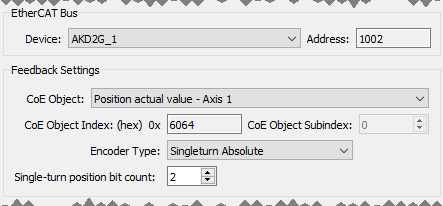
Figure 4-21: PLCopen Axis - Bus Parameters
The EtherCAT device parameters are:
| Parameter | Description |
|---|---|
| Device | Select the device that will provide the digitizing axis feedback. The list is populated by the devices defined in the EtherCAT section of the Project View. 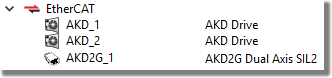 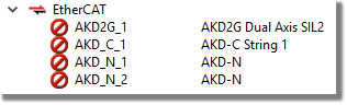 |
| Address | The digitizing Address is the EtherCAT address of the device in the network. It is the 4-digit node address of the servo drive
|
| CoE Object | Select the item that will be used to read the feedback. |
| CoE Object Index | The CoE object index of the feedback device |
| CoE Object Sub-Index | The sub-index of the feedback device. This is a decimal value, |
| Encoder Type | Select Singleturn Absolute or Multiturn Absolute. |
| Single-turn position bit count | Typically 12, 16, 20, or 32-bits. A value of "0" indicates that rollover is not applicable. |
-
- AKD2G: Digitizing axes mapped to an AKD2G device are particularly easy to work with.
- The PDO 0x1A01 is automatically populated with available feedbacks.
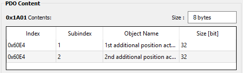
- When a feedback object 0x60E4:1 to 0x60E4:2 is selected, the Encoder Resolution is automatically set to 31 bits and the Feedback Units field is initialized to the 231 value.
- The Feedback Units text box is automatically adjusted to 2(Encoder Resolution) when the Encoder Resolution is changed.
- Feedback units will be configured on the AKD2G device based on the resolution specified for the digitizing axis. This is done using init commands during project compilation.
- The PDO 0x1A01 is automatically populated with available feedbacks.
-
-
For more information see Working With A Digitizing Axis in PLCopen.


