Emergency Object (EMCY)
EMCY is event-triggered and generated by an internal fault/error situation. This object is transmitted afresh for every error. The last 10 Emergency error codes can be read using object 1003.
Application of the Emergency Object
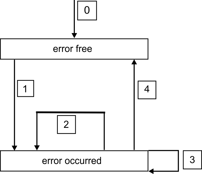
The reaction in the event of an error or fault depends on the error class and its variable. For this reason, the reaction is described with the aid of an error state machine. The error conditions error-free and error occurred are distinguished. Defined transitions:
Transition 0: After initialization, the error-free status is taken up if no errors are detected.
No error signal is generated in this condition.
Transition 1: The AKD detects an internal error and indicates this in the first three bytes of the emergency telegram (error code in Bytes 0,1 and error register in Byte 2).
Transition 2: One error has been reset, but not all. The EMCY telegram contains error code 0000 and the error register indicates the remaining errors that are present. The manufacture-specific area is set to zero.
Transition 3: A new error has occurred. The AKD remains in the error status and transmits an EMCY Object with the corresponding error code. The new error code is entered into bytes 0 and 1.
Transition 4: All errors have been reset. The EMCY telegram contains the error code 0000. The error register does not indicate any other errors. The manufacture-specific area is set to zero.

Composition of the Emergency Object
The Emergency Object is composed of 8 bytes, divided as follows:
| Byte | Bit | Content |
|---|---|---|
| 0 | Emergency error code | |
| 1 | ||
| 2 | Error register (object 1001h) | |
| 3 | 0-3 | Axis id |
| 4-7 | Feedback id | |
| 4 | Reserved | |
| 5 | ||
| 6 | ||
| 7 |
If an Emergency Object is generated, the error condition is then signaled to the state machine (error free/error occurred) by the generation of a second Emergency Object. Only the first four bytes are relevant in this case (Emergency Error code, Error register, Axis Id). Byte 0/1 contains the Emergency Error Code (0000) and Byte 2 indicates if a possible further error is present. If the error register contains 00, the error status is error-free. Byte 3 contains the axis id that the error occurred in bits 0 – 3 (value 1 means Axis 1) and the feedback id. If a feedback fault occurred in the bits 4 to 7 (values 1..5 mean FB1..FB5). The interpretations of the error numbers error codes are described in the section Error Codes. The error register is defined by object 1001.


