Touch Probes
Each touch probe can capture two positions, the position on the rising and the position of the falling edge of the trigger input.
The AKD2G touch probes conform with the EtherCAT![]() EtherCAT is an open, high-performance Ethernet-based fieldbus system. The development goal of EtherCAT was to apply Ethernet to automation applications which require short data update times (also called cycle times) with low communication jitter (for synchronization purposes) and low hardware costs ETG6010 specification “CiA402 Implementation Directive” and CANopen DS402.
EtherCAT is an open, high-performance Ethernet-based fieldbus system. The development goal of EtherCAT was to apply Ethernet to automation applications which require short data update times (also called cycle times) with low communication jitter (for synchronization purposes) and low hardware costs ETG6010 specification “CiA402 Implementation Directive” and CANopen DS402.
On AKD2G, the touch probes are separate from the drive's position capture channels, CAP1 and CAP2. The touch probes use their own dedicated hardware in the drive. The configuration and status of the touch probes will not be available by the CAP#. keywords.
These are the EtherCAT/CANopen objects AKD2G supports.
| Axis 1 Index | Axis 2 Index | Name |
|---|---|---|
| 60B8h | 68B8h | Touch probe function / control |
| 60B9h | 68B9h | Touch probe status |
| 60BAh | 68BAh | Touch probe 1 position positive value |
| 60BBh | 68BBh | Touch probe 1 position negative value |
| 60BCh | 68BCh | Touch probe 2 position positive value |
| 60BDh | 68BDh | Touch probe 2 position negative value |
| 60D0h | 68D0h | Touch probe source |
| 60D1h | 68D1h | Touch probe 1 time stamp positive value |
| 60D2h | 68D2h | Touch probe 1 time stamp negative value |
| 60D3h | 68D3h | Touch probe 2 time stamp positive value |
| 60D4h | 68D4h | Touch probe 2 time stamp negative value |
| 60D5h | 68D5h | Touch probe 1 positive edge counter |
| 60D6h | 68D6h | Touch probe 1 negative edge counter |
| 60D7h | 68D7h | Touch probe 2 positive edge counter |
| 60D8h | 68D8h | Touch probe 2 negative edge counter |
60D0h, 68D0h, Touch Probe Source. The following table shows how AKD2G signals are mapped to the touch probe source entry in the object dictionary
-
- A few sources appear in both the standard and the manufacturer specific ranges to provide consistency.
| 60D0h,68D0h | Description |
|---|---|
| -41 to -42 | Z pulse for Axis 1 to 2 |
| -31 to -35 | Z pulse for Feedback 1 to 5 As FB1, 2, 4, and 5 do not support Z pulses then these will not be shown. When we support SFA on FB 1 and 2 then Z pulse may be possible. X23 is optional so if not fitted then -33 will not be valid. |
| -21 to -26 | DIO1 to DIO6 When X22 is not fitted options -21 and -22 will not be valid. When X23 is not fitted options -23 to -26 will not be valid. |
| -1 to -12 | DIN1 to DIN12 When X22 is not fitted options -9 to -12 will not be valid. |
| 0 | Reserved |
| 1 | DIN1. Fast Opto |
| 2 | DIN2. Fast Opto |
| 3-4 | Reserved |
| 5 | Valid if PL.FBSOURCE is using a feedback that supports a Z pulse. |
| 6 to 32767 | Reserved |
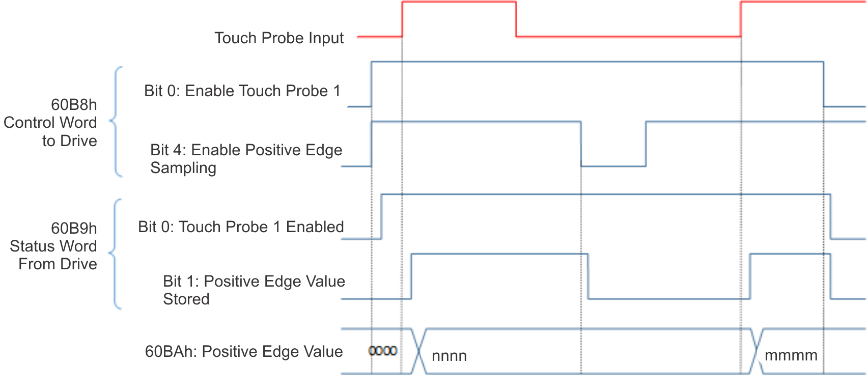
The following diagram shows the sequence for controlling the touch probe feature.


