 Position Loop
Overview
The position loop is active when the drive operates in position mode (AXIS#.OPMODE
Tabs in the Position Loop View
The position loop view includes an active block diagram. If you click on a block in the diagram, the appropriate tab opens below.
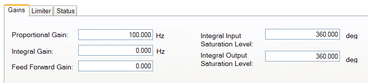
- Gains. This tab shows the gains for the position loop.
-
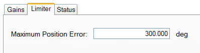
Limiter. The value in the Maximum Position Error box (AXIS#.PL.ERRFTHRESH ) limits the position error (AXIS#.PL.ERR PL.ERR ) that can be present. When the maximum position error is exceeded, the drive generates fault F6001 , Following Error. If the maximum position error is set to 0 (default) then the maximum position error is ignored.
Limiter. The value in the Maximum Position Error box (PL.ERRFTHRESH ) limits the position error (PL.ERR ) that can be present. When the maximum position error is exceeded, the drive generates fault F439 n439 , Following Error. If the maximum position error is set to 0 (default) then the maximum position error is ignored.
-
Status. This tab shows the present value of commanded position (AXIS#.PL.CMD ), position feedback (AXIS#.PL.FB ), position error (AXIS#.PL.ERR ), and velocity command (AXIS#.VL.CMD).
Status. This tab shows the present value of commanded position (PL.CMD ), position feedback (PL.FB ), position error (PL.ERR ), and velocity command (VL.CMD ).
Position Loop Default Behavior and Changes
By default, only a proportional gain
Position Loop Changes Based on Slider Tuning
Slider Tuning (see Slider Tuning) adjusts the proportional gain of the position loop (along with velocity loop view parameters; see Velocity Loop). If you adjust the bandwidth![]() In computer networking, bandwidth often refers to a data rate measured in bits/s, for example, network throughput. The reason for the connection of data rate with the term bandwidth is that the limit to the data rate of a physical communication link is related to its bandwidth in hertz using the slider tuner, then when you return to the position loop screen, you will see a change to the proportional gain only. No adjustment is made to the integral gain or feedforward gain through the slider tuner. The integral saturation levels are not applicable when the integral gain is set to 0. In the Gains tab, the boxes for these values may be populated with default values whether or not the integral gain is set to 0.
In computer networking, bandwidth often refers to a data rate measured in bits/s, for example, network throughput. The reason for the connection of data rate with the term bandwidth is that the limit to the data rate of a physical communication link is related to its bandwidth in hertz using the slider tuner, then when you return to the position loop screen, you will see a change to the proportional gain only. No adjustment is made to the integral gain or feedforward gain through the slider tuner. The integral saturation levels are not applicable when the integral gain is set to 0. In the Gains tab, the boxes for these values may be populated with default values whether or not the integral gain is set to 0.
Related Parameters


