Using Wake and Shake Mode 0 (AXIS#.WS.MODE 0)
Overview
Wake and shake (WS) is used to establish commutationfor motors and is required for the following applications:
- Incremental encoders without Halls or commutation channels.
- Sine encoders without Halls or commutation channels.
- Motor with Halls which were not aligned to be at 0 degrees motor phase.
When controlling a brushless DC (BLDC) motor, you must know the electrical position of the motor shaft. Without absolute position data, it is impossible for the drive to know which sequence of coils to energize to produce motion. Absolute feedback devices, such as resolvers and absolute encoders, can detect position directly. Incremental devices, such as incremental encoders and sine encoders without a commutation channel, must determine electrical position indirectly at start up. The drive uses the WS feature to determine electrical position by sending the motor short bursts of current and measuring the resulting incremental motion. The drive uses this measurement to estimate electrical position accurately enough to control the AXIS#.MOTOR.
Configuring WS
You can configure WS after your motor has been connected to the AKD2G according to the AKD2G Installation Manual. The WS procedure is initiated automatically when both the hardware and software enable signals become logic high.
Before attempting to enable an axis, the axis must be compensated for the motor and the AKD2G servo loops must be stable.
Compensation values for many rotary motors are included in a database already loaded into the drive.
-
-
An unstable system will not function properly during or after the WS process.
Use the default Wake and Shake view to configure your system:
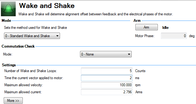
Arm
Click Arm to set WS to start at the next axis enable (AXIS#.WS.ARM ). This area also shows the current status of the wake and shake process. See AXIS#.WS.STATE for a detailed explanation of the possible states.
AXIS#.WS.ARM is not restricted to any feedback type.
Commutation Check
Select the type of commutation check to execute after Wake and Shake finds a new commutation angle.
0 - None: No Commutation Check
If No Commutation Check is selected, neither passive nor active commutations checks will be executed.
1 - Active: (default)
In the default Active Commutation Check mode, AKD2G will make a short torque![]() Torque is the tendency of a force to rotate an object about an axis. Just as a force is a push or a pull, a torque can be thought of as a twist move after an angle has been selected. If the motor fails to move in the expected direction, a fault will be generated.
Torque is the tendency of a force to rotate an object about an axis. Just as a force is a push or a pull, a torque can be thought of as a twist move after an angle has been selected. If the motor fails to move in the expected direction, a fault will be generated.
2 - Passive:
In the Passive Commutation Check mode, AKD2G will monitor torque commands and acceleration values for 10 revolutions after Wake and Shake has completed. During this time, a fault will be generated if unexpected motion is detected, such as if commanded torque and acceleration are in opposition directions. Note that this fault may also be reported if the motor experiences a large torque disturbance lasting longer than AXIS#.WS.CHECKT.
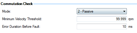
Minimum Velocity Threshold: sets the value which must be exceeded to activate commutation monitoring.
Error Duration Before Fault: sets the amount of time a commutation error must be present before a fault is generated.
Settings
- Number of Wake and Shake Loops (AXIS#.WS.NUMLOOPS ). The WS feature uses the mean of all wake and shake repetitions, called "loops", to establish commutation (see Using WS: Advanced for a discussion of loops). If fewer than five loops are used, commutation may be incorrect, possibly causing poor performance or stability.
- Time the current vector applied to AXIS#.MOTOR. (AXIS#.WS.T ). This box specifies the duration of the current pulse used for commutation. Increasing this value increases the movement of the system.
- Maximum allowed velocity (AXIS#.WS.VTHRESH ). If a velocity (AXIS#.VL.FB ) higher than this value is detected while WS is running, then a fault will be generated.
- Maximum allowed current (AXIS#.WS.IMAX ). This value is directly proportional to the movement. A value that is too low may fail to cause movement; a value that is too high value may cause an over speed fault.
- Maximum allowed movement (AXIS#.WS.DISTMIN ). If the total motion from the starting position is less than AXIS#.WS.DISTMIN a fault will occur. This will prevent poor initialization from broken wires, incorrect current settings, very high friction, etc. Setting AXIS#.WS.DISTMIN to zero disables this feature.
- Minimum allowed movement (AXIS#.WS.DISTMAX ). If the total motion from the starting position (the position at the time the axis is enabled after a AXIS#.WS.ARM command) exceeds AXIS#.WS.DISTMAX a fault will occur. Setting AXIS#.WS.DISTMAX to zero disables this feature.
Wake and Shake, More View
To configure additional WS settings, click More at the bottom of the default view to display the following
options:
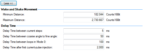
Wake and Shake Movement
Use these boxes to set values for the maximum (AXIS#.WS.DISTMAX ) and minimum (AXIS#.WS.DISTMIN ) movement required for finding commutation.
Delay Times
Delay time is the time that elapses when switching different current vectors. Use these boxes to set specific time delays for current steps (AXIS#.WS.TDELAY1 ), coarse to fine angle (AXIS#.WS.TDELAY2 , time between loops in mode 0 (AXIS#.WS.TDELAY3 ), and time after first current-pulse injection (AXIS#.WS.TDELAY4).
Special Cases for WS
Operation with Motor Brake
An amplifier with a motor brake operates the WS procedure similar to an amplifier without a brake. All precautions and behavioral descriptions above also apply in this case. It is important to note that the brake is automatically applied (motor brake, not holding brake) after the WS process is complete. The brake may cause unexpected movement if the AXIS#.OPMODE used prior to WS does not retain position. If a force component is present tangential to the track on a rotary motor, the motor may move from the startup position after WS completes and the brake is applied.
If the application requires that the startup position be retained, have the controller system ready to take control immediately after WS is complete. One way to set this control is to have the axis in AXIS#.OPMODE 1 (digital velocity) or AXIS#.OPMODE 2 (position mode) on power-up. This precaution keeps the motor stationary after enable.
End of Travel Limits
If anything restricts the motion of the motor, a commutation fault can occur. Examples of situations that may result in faults include the following:
- If the motor is resting against a rigid end stop, the movement of the motor may be impeded below the minimum threshold set by AXIS#.WS.DISTMIN. This lack of movement causes a fault.
- If the motor is actuating a limit sensor
 A sensor is a type of transducer that converts one type of energy into another for various purposes including measurement or information transfer/switch, the system (PLC"Programmable Logic Controller"
A Programmable Logic Controller, PLC, or Programmable Controller is a digital computer used for automation of industrial processes, such as control of machinery on factory assembly lines.
Used to synchronize the flow of inputs from (physical) sensors and events with the flow of outputs to actuators and events, AXIS#.SWLS.LIMIT#) may be preventing the AKD2G from producing motion. If descriptive motion is not achieved, the system faults.
A sensor is a type of transducer that converts one type of energy into another for various purposes including measurement or information transfer/switch, the system (PLC"Programmable Logic Controller"
A Programmable Logic Controller, PLC, or Programmable Controller is a digital computer used for automation of industrial processes, such as control of machinery on factory assembly lines.
Used to synchronize the flow of inputs from (physical) sensors and events with the flow of outputs to actuators and events, AXIS#.SWLS.LIMIT#) may be preventing the AKD2G from producing motion. If descriptive motion is not achieved, the system faults.
Large Load Inertia or High Friction System
Systems with a large load mismatch may need more current than the default setting for correct commutation. Begin with the default value for AXIS#.WS.IMAX and gradually increase or decrease as needed. If adjusting AXIS#.WS.IMAX does not result in a successful commutation, the width of the search pulse can be increased by increasing AXIS#.WS.T .
Using WS: Advanced
WS is performed upon enable in order to establish a valid value for AXIS#.MOTOR.PHASE at startup. AXIS#.MOTOR.PHASE is used to calculate electrical phase. With absolute feedback devices, AXIS#.MOTOR.PHASE is a fixed offset between absolute mechanical position and the electrical position. With incremental devices, position is accumulated relative to an initial AXIS#.MOTOR.PHASE. However, at startup, AXIS#.MOTOR.PHASE is invalid since the initial position is random, thus the requirement for the WS process.
WS is a two-step process:
- Coarse Phase. The drive sequentially pulses a user-specified current, AXIS#.WS.IMAX , at each electrical quadrant (0°, 90°, 180°, 270°). Based on the resulting observed movement, an approximate location is calculated.
- Fine Phase. The drive makes small adjustments to the coarse phase while monitoring movement during velocity mode (command velocity = 0) to find a precise position.
The amplitude of the current pulses in this process equals AXIS#.WS.IMAX. The drive repeats these two steps for a user-specified number of times (AXIS#.WS.NUMLOOPS ) to produce a more accurate estimate of the electrical phase.
The drive normally indicates warning W5500 before WS is initiated and successful. If WS fails, the commutation is not valid and the drive indicates one of the following faults:
- F5500 : Insufficient movement. The maximum movement during WS was less than AXIS#.WS.DISTMIN .
- F5501 : Excessive movement. The movement during WS exceeded AXIS#.WS.DISTMAX .
- F5502 : Fine-Coarse delta too large. The phase calculated during the fine phase and coarse phase differed by more than 10 degrees.
- F5503 : Over speed. The feedback velocity (AXIS#.VL.FB ) exceeded AXIS#.WS.VTHRESH .
- F5504 : Loop angle delta too large. The difference between the phase determined in different cycles (loops) exceeded 30 degrees.
- F5505 : Commutation not initialized. WS is required (feedback is one of the types listed in the Overview) but WS has not been successfully performed.
- F5506 to F5508 : U, V, or W phase missing . Intermittent or broken motor connection.
Maximizing WS Reliability
The following suggestions will help you achieve successful commutation:
- Incorrect determination of AXIS#.MOTOR.PHASE may cause a system runaway. Since the typical movement during correct operation of WS is very small, you can use the velocity overspeed parameters (AXIS#.WS.VTHRESH and DRV.VTHRESH) to prevent a runaway. Prior to enabling the drive, set DRV.VTHRESH 200 rpm for rotary motors. After a successful enable, DRV.VTHRESH can be returned to the normal operating value.
- Set AXIS#.WS.IMAX to its default value, AXIS#.WS.IMAX=0.5*min(AXIS#.MOTOR.IPEAK, AXIS#.IPEAK).
- Set AXIS#.WS.NUMLOOPS 20 for best results in many applications.
- AXIS#.WS.T specifies the duration for which the search current is applied. With a stable velocity loop, most applications work well with the default value of AXIS#.WS.T. The default value causes the software to calculate the width of the search pulse based on the velocity loop proportional gain, AXIS#.VL.KP. Increasing AXIS#.WS.T effectively increases the movement of the motor during WS, which may be necessary for systems with a low-resolution feedback or high load inertia.
- AXIS#.WS.IMAX specifies the amplitude of the current pulse used during the initial/rough commutation. An AXIS#.WS.IMAX value that is too low may result in a fault by failing to cause enough movement for commutation. If the value is too high, the preset movement threshold could be exceeded, also resulting in a fault. If the default value is producing faults for too little movement, gradually adjust this parameter to overcome excessive friction and/or load on the system. AXIS#.WS.IMAX also specifies the maximum current used in the second stage of commutation. The initial current is 25% of AXIS#.WS.IMAX, then steps up to 100% of AXIS#.WS.IMAX.
- FB#.SELECT selects the type of feedback used by the amplifier. The WS feature is used only for FB#.SELECT = 11, 21. The feedback must be configured prior to initiating the WS procedure.
- If your amplifier has a motor brake, set AXIS#.MOTOR.BRAKE = 1. For motors without a brake, set AXIS#.MOTOR.BRAKE = 0.
-
-
- Adjust AXIS#.WS.T with extreme caution. Increasing AXIS#.WS.T increases the movement of the system. Applying an incorrect value of AXIS#.WS.T may cause erratic drive behavior.
- When initiating WS, the motor may experience a runaway. Stay clear of all moving parts. Ensure there are properly operating safety devices such as hardware limit switches and suitable end-of-travel limits.
- If AXIS#.WS.NUMLOOPS is less than 5, commutation may be incorrect. This condition may cause faults and/or adversely affect performance or stability. Set AXIS#.WS.NUMLOOPS = 20.
Troubleshooting WS
| Problem | Possible Cause | Remedy |
|---|---|---|
|
Excessive Movement |
|
|
|
Insufficient Movement |
|
|
|
U, V, or W Phase Missing Fault |
Intermittent or broken motor connection. |
Check connections to motor phases. |
|
Commutation Not Initialized Fault |
Wake and Shake is required but WS procedure has previously been canceled (AXIS#.WS.DISARM) or has failed. |
Correct errors and rerun WS procedure. |
|
Other |
|
|
Related Parameters


