Cut to Length (Index – Stop) Pipe Network
Introduction
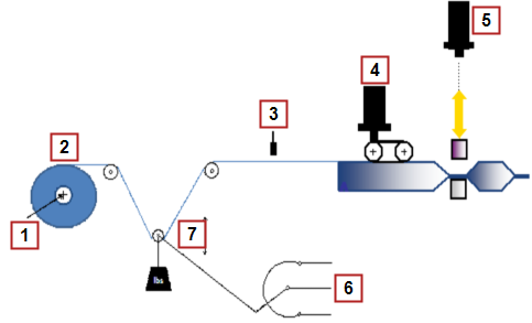
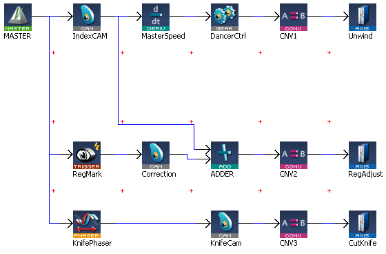
This application module details a 3 axis section of machine containing an unwind axis with dancer control, registration mark control axis making adjustments based on product registration marks, and a cutting knife axis using the Pipe Network motion engine. The unwind axis maintains a desired tension on the product as the registration mark control axis; using registration marks on the product; positions the product. When in position the cutting knife will cut the product to the desired length.

|
|
The combination of pipeblocks and PLC![]() "Programmable Logic Controller"
A Programmable Logic Controller, PLC, or Programmable Controller is a digital computer used for automation of industrial processes, such as control of machinery on factory assembly lines.
Used to synchronize the flow of inputs from (physical) sensors and events with the flow of outputs to actuators and events code can easily be modified for use in a variety of cut to length applications, by modifying the CAM profiles and machine cycle times to fit machines with varying mechanics and desired material cut lengths.
"Programmable Logic Controller"
A Programmable Logic Controller, PLC, or Programmable Controller is a digital computer used for automation of industrial processes, such as control of machinery on factory assembly lines.
Used to synchronize the flow of inputs from (physical) sensors and events with the flow of outputs to actuators and events code can easily be modified for use in a variety of cut to length applications, by modifying the CAM profiles and machine cycle times to fit machines with varying mechanics and desired material cut lengths.

Unwind Axis
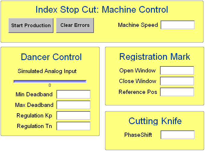
The unwind axis is geared to the virtual master axis based on a profile (IndexCAM). As the product is being unwound from the parent roll a dancer roll is monitoring the desired tension. If the tension is outside the desired adjustable dead band the gear ratio between the virtual master axis and unwind is adjusted to maintain the desired tension. The tension (Regulation Tn), gain to control the tension (Regulation Kp), minimum and maximum dead band (Deadband Min & Deadband Max) is entered on the control panel.

Figure 7-254: Unwind Base Profile
Registration Mark Control Axis
The registration mark control axis monitors the registration marks on the product and adjusts the product based on the registration mark parameters, Open Window, Close Window, and Reference Pos entered on the operator panel. If the registration mark is detected between the Open Window and Close Window the registration mark is considered a good mark and the Reference Pos value will be used to calculate the necessary adjustment. If the registration mark is detected outside the Open Window and Close Window values then the registration mark is ignored. Adjustments are not made during the cutting process to avoid destroying product.
Cutting Knife Axis
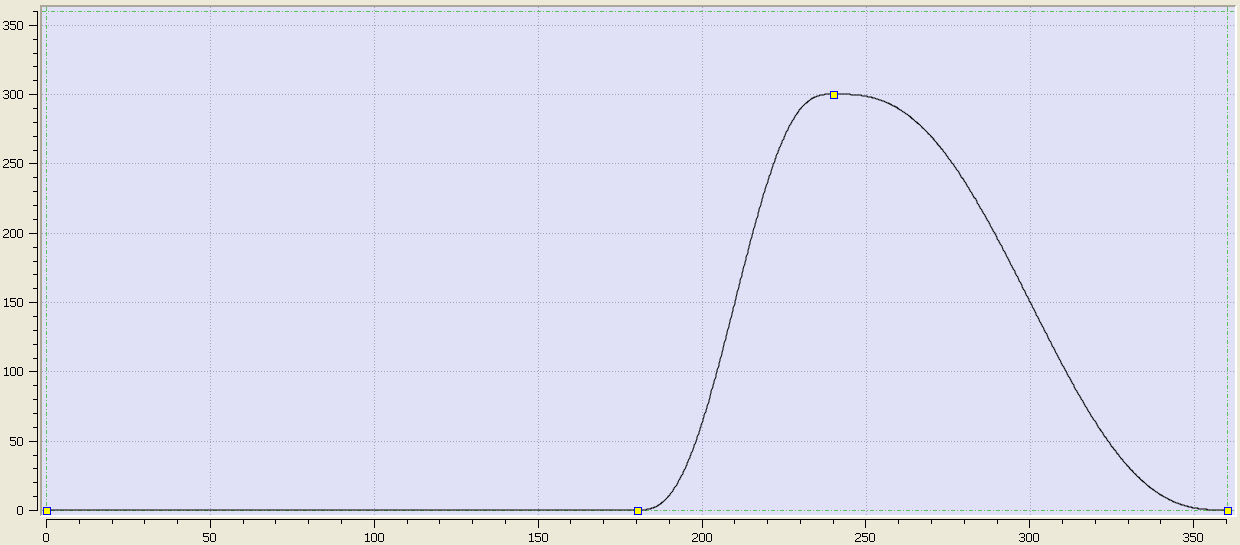
The cutting knife axis is geared to the master virtual axis based on a profile (CutKnifeCAM). The profile will start at the starting position of the virtual axis.

Figure 7-255: Cutting Knife Base Profile
PLC Program Code
Key Function![]() A function calculates a result according to the current value of its inputs. A function has no internal data and is not linked to declared instances. Blocks and Kollmorgen UDFBs used in the application
A function calculates a result according to the current value of its inputs. A function has no internal data and is not linked to declared instances. Blocks and Kollmorgen UDFBs used in the application
| Name | How Used |
|---|---|
|
MLMstRun |
Jog at a specified speed |
|
MLMstWriteSpeed |
Set the speed of a master block |
|
MLMstAbs |
Performs a move to an absolute position |
|
MLGearWriteRatio |
Set the gear ratio between two axes |
|
MLBlkReadOutVal |
Get the output value of a pipe block |
|
MLTrigIsTrigged |
Checks if a block is triggered |
|
MLTrigReadPos |
Returns the position of the block |
|
MLTrigClearFlag |
Clears the flag of a triggered block |
|
MLAxisRstFastIn |
|
|
MLPrfWriteOScale |
Set the output ratio of a cam profile |
|
MLPhaWritePhase |
Set the phase of a phase block |
The main section of the PLC code contains several If/Then statements. The program sets up gearing and cam profiles for the slave axis to a virtual master. The virtual master controls the machine speed. The slave axes are manipulated by either changing the operator panel inputs or profiles. The program is monitoring registration marks on the product and making correction to the product position based on the entries at the operator panel.
//****************
// Machine Control
//****************
IF bStart THEN
fStart(bStart);
IF OldMachineSpeed<>MachineSpeed THEN
MLMstRun(PipeNetwork.MASTER, MachineSpeed);
OldMachineSpeed:=MachineSpeed;
END_IF;
ELSE
IF fStart.Q THEN
MLMstWriteSpeed(PipeNetwork.MASTER, MachineSpeed);
MLMstAbs(PipeNetwork.MASTER, 720.0);
OldMachineSpeed:=0.0;
END_IF;
END_IF;
//***************
// Dancer Control
//***************
// Range 0-10V, 5V mid, 4-6V Deadband, <4V increase speed, >6V decrease speed
IF bStart THEN
Inst_UwindAnalogDancerControl( TRUE, AnaInDancer, Kp, Tn, MinDeadBand, MaxDeadBand, 1000 );
IF Inst_UwindAnalogDancerControl.obOutsideDeadband THEN
MLGearWriteRatio(PipeNetwork.DancerCtrl, (LREAL#1.0+Inst_UwindAnalogDancerControl.oUnwindGearRatio));
END_IF;
END_IF;
//*****************************************
// Transport axis with registration control
//*****************************************
//Inside window for good marks
IF MLBlkReadOutVal(PipeNetwork.MASTER)>OpenWindow AND MLBlkReadOutVal(PipeNetwork.MASTER) < CloseWindow THEN
IF MLTrigIsTrigged(PipeNetwork.RegMark) THEN
CorrLength:=MLTrigReadPos(PipeNetwork.RegMark)-ReferencePos;
IF CorrLength>MaxCorrLength THEN
CorrLength:=MaxCorrLength;
ELSIF CorrLength< -MaxCorrLength THEN
CorrLength:=-MaxCorrLength;
END_IF;
END_IF;
ELSE
//outside window ignore marks and reset if fast input is triggered
IF MLTrigIsTrigged(PipeNetwork.RegMark) THEN
MLTrigClearFlag(PipeNetwork.RegMark);
MLAxisRstFastIn(PipeNetwork.RegAdjust, 0);
END_IF;
END_IF;
ON MLBlkReadOutVal(PipeNetwork.MASTER) > 10 DO
MLPrfWriteOScale(Profiles.RegAdjustCAM, CorrLength);
END_DO;
//**************
// Cutting Knife
//**************
IF PhaseKnife <> OldPhaseKnife THEN
MLPhaWritePhase(PipeNetwork.KnifePhaser,PhaseKnife);
OldPhaseKnife := PhaseKnife;
END_IF;
//******************
// Reset axis errors
//******************
IF bReset THEN
MLAxisClrErrors(PipeNetwork.Unwind);
MLAxisClrErrors(PipeNetwork.RegAdjust);
MLAxisClrErrors(PipeNetwork.CutKnife);
bReset := FALSE;
END_IF;
Operator Panel
The Kollmorgen Automation Suite (KAS) program for this application module has an internal operator panel. The operator panel is used to set the desired values for each product and to start and stop the machine. The specific entries are described in the axis sections above. Below is a screen print of the operator panel.


