Connecting a DDL Motor to an AKD Drive
Before Connecting a DDL motor to an AKD drive, the following tasks must be accomplished:
- Integrate motor coil and magnet way onto a bearing structure so that the motor moves freely (rubber stops at the end of travel are recommended, especially during commissioning).
- Linear scale is integrated to the assembly and set up with the correct alignment and airgap to provide an appropriate sinusoidal or digital feedback signal.
- Determine the resolution of the Linear Scale in micrometers (microns) per cycle (this will be listed in the documentation of the linear scale).
Connect Hall sensor![]() A sensor is a type of transducer that converts one type of energy into another for various purposes including measurement or information transfer, Linear Scale, and motor temperature cables through the ACI-AKD cable assembly to the AKD's X10 Feedback Connector.
A sensor is a type of transducer that converts one type of energy into another for various purposes including measurement or information transfer, Linear Scale, and motor temperature cables through the ACI-AKD cable assembly to the AKD's X10 Feedback Connector.
Connect the motor power leads to the AKD motor power connector X2 with the following connections:
Red -> U
White -> V
Black -> W
Yellow / Green -> PE
Apply 24 volt logic power to the AKD and launch KAS IDE![]() "Integrated development environment"
An integrated development environment is a type of computer software that assists computer programmers in developing software.
IDEs normally consist of a source code editor, a compiler and/or interpreter, build-automation tools, and a debugger from a computer to interface with the AKD drive.
"Integrated development environment"
An integrated development environment is a type of computer software that assists computer programmers in developing software.
IDEs normally consist of a source code editor, a compiler and/or interpreter, build-automation tools, and a debugger from a computer to interface with the AKD drive.
-
-
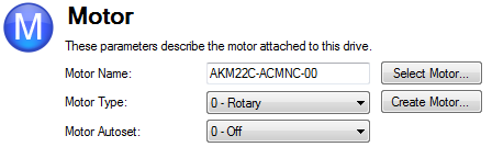
If “Select Motor” is grayed out, Motor Autoset may need to be set to “0 –Off” to enable the Select Motor option.
On the Select Motor screen, for Motor Family select either IC![]() "Integrated Circuits"
Miniaturized electronic circuits (consisting mainly of semiconductor devices, as well as passive components) that have been manufactured in the surface of a thin substrate of semiconductor material and ICD Series Ironcore DDL or IL
"Integrated Circuits"
Miniaturized electronic circuits (consisting mainly of semiconductor devices, as well as passive components) that have been manufactured in the surface of a thin substrate of semiconductor material and ICD Series Ironcore DDL or IL![]() "Instruction list"
This is a low-level language and resembles assembly Series Ironless DDL. On the Select Motor screen for “Name” select the appropriate motor part number.
"Instruction list"
This is a low-level language and resembles assembly Series Ironless DDL. On the Select Motor screen for “Name” select the appropriate motor part number.
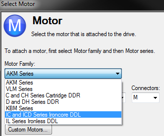
Click OK.
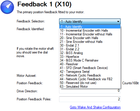
From the main tree, under Settings, select Feedback 1.
Under Feedback Selection, select either 10 – Incremental Encoder with Halls
Using the resolution of the Linear Scale in Microns per cycle, the Sine Cycles/Magnet Pitch is determined. Use the following:
1. Take the reciprocal of resolution to get cycles per micron
2. Multiply by 1000 to get cycles per millimeter
3. Multiply by 32 millimeters per Magnet Pitch to get Sine Cycles/Magnet Pitch
For example, if the resolution of the Linear Scale is 40 microns per cycle, then the Sine Cycles/Magnet Pitch would be 800.
The Linear Scale phase direction must be verified. Watch the Feedback 1 screen in WorkBench. When the coil assembly is moved in the direction of the cable exit (think of pulling the coil by the cable), the Position Feedback should increase positively in value and in the motor graphic, the gray block should move to the right. If the direction is opposite, then the A+ and A- signals on the Linear Scale must be swapped to correct the phase direction.
The motor is now ready for velocity loop and position loop compensation.


