 MLAxisAbs
Description
Performs a move to an absolute position. Returns TRUE if the function succeeded.
Arguments
Input
|
ID |
Description |
ID name of the Axis Block |
|
Data type |
DINT |
|
|
Range |
[-2147483648, 2147483648] |
|
|
Unit |
N/A |
|
|
Default |
— |
|
|
Position |
Description |
Sets the value of the absolute destination position. When the Modulo is turned on, see more explanations below. |
|
Data type |
LREAL |
|
|
Range |
— |
|
|
Unit |
||
|
Default |
— |
|
|
Default (.Q) |
Description |
Returns true when function successfully executes See more details here. |
|
Data type |
BOOL |
|
|
Unit |
N/A |
Position with Modulo On
-
- This information applies to both MLMstAbs and MLAxisAbs. For simplicity, the term Axis Block also refers to Master Block.
When the Modulo is turned on, the Axis Block moves to the targeted position during the corresponding period, calculated as follows:
- If the Position input is between 0 and the Modulo Position, then the Axis Block moves within the current period (no position rollover).
- If the Position input is greater than the Modulo Position, then the Axis Block moves during one of the next period (positive position rollover).
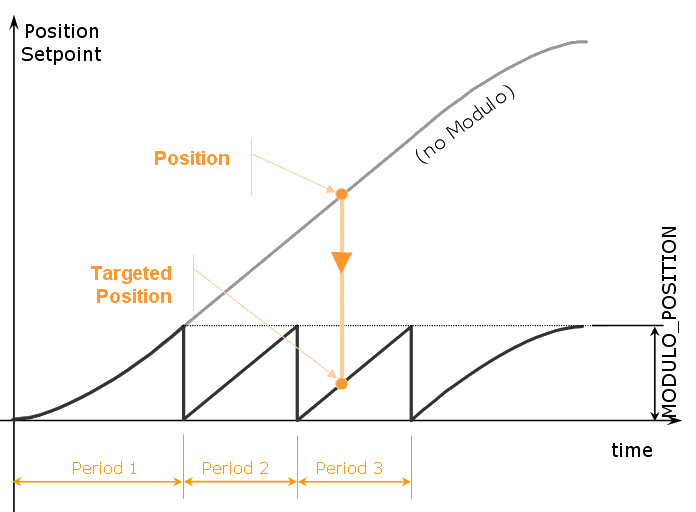
The Axis Block works similarly for negative positions: if the Position input is less than zero, then the Axis Block moves during one of the previous period (negative position rollover).
Forcing the direction of rotation
In some applications, the direction of rotation for the axis is forced in one direction only. As a consequence, the motor movement goes to the next or previous modulo in the following situations:
- If the End Position is less than the Start Position and the direction of rotation for the axis is forced to be clockwise (the red point shows when the modulo position is reached).
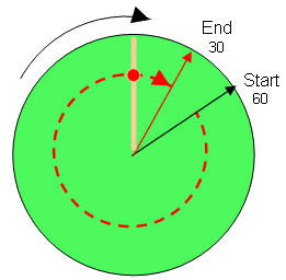
(see an example in row#2 of the table below) - If the End Position is greater than the Start Position and the direction of rotation for the axis is forced to be counter clockwise.
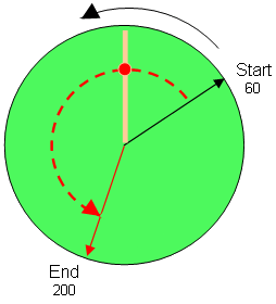
(see an example in row#4 of the table below)
Examples
| Start Position | End Position | Direction of rotation | Cross Modulo | Position Input to MLAxisAbs (1) | RelativeDistance Moved (2) | |
| 60 | 200 | clockwise | No | 200 | 140 | (i.e. 200 - 60 + 0) |
| 60 | 30 | clockwise | Yes | 390 | 330 | (i.e. 30 - 60 + 360) |
| 60 | 30 | counter clockwise | No | 30 | -30 | (i.e. 30 - 60 - 0) |
| 60 | 200 | counter clockwise | Yes | -160 | -220 | (i.e. 200 - 60 - 360) |
With:
|
(1) Position Input = End Position ( + Modulo * Direction of rotation)
(2) Relative Distance Moved = End Position - Start Position ( + Modulo * Direction of rotation) |
Where:
|
Direction of rotation = 1 when clockwise and -1 when anti-clockwise |
Travel Speed Update with MLAxisAbs
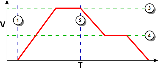
The travel speed of the generator can be updated using the function block MLAxisGenWriteSpd. Depending on the state of the generator, this speed is directly reflected on the current move or a future move.
- If MLAxisAbs is not currently being executed, the new travel speed will be applied for the trajectory calculation for a future MLAxisAbs command.
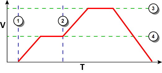
- If MLAxisAbs is currently being executed and a new MLAxisAbs with the same target position is called, the new travel speed will be taken into account only if the current state of the TMP
 "Trapezoidal Motion Profile"
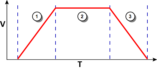
This pipe block is a source block that frequently serves as a virtual master for a system composed of several pipes. Generally, a trapezoidal motion profile generator is used to generate a flow of values with a first derivative which produces a trapezoidal trajectory profile is the constant velocity or acceleration. If the axis was decelerating to stop at the goal position the new travel speed will not be taken into account.
 - If a MLAxisAbs is currently being executed and a new MLAxisAbs with a different target position is called, the new travel speed is taken into account.
Following are several examples.
|
|
Figure 8-77: Initial speed is smaller than the new speed
|
|
Figure 8-78: Initial speed is bigger than the new speed
|
|
Figure 8-79: The speed update is taken into account only if the second MLAxisAbs is triggered during acceleration or constant velocity
Related Functions
Example
See Usage Example of Axis Functions for additional examples.
Structured Text
|
MLAxisAbs( PipeNetwork.Axis1, 2000 ) ;
|
Ladder Diagram

Function Block Diagram

 [Top]
[Top]


