Cut to Length (Index – Stop) PLC Open
Introduction
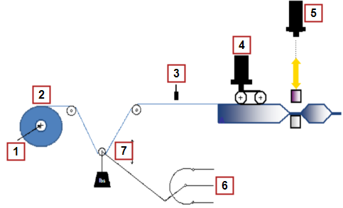
This application module details a 3 axis section of machine containing an unwind axis with dancer control, registration mark control axis making adjustments based on product registration marks, and a cutting knife axis using the PLCopen![]() A vendor -and product- independent worldwide association active in Industrial Control and aiming at standardizing PLC file formats based on XML motion engine. The unwind axis maintains a desired tension on the product as the registration mark control axis; using registration marks on the product; positions the product. When in position the cutting knife will cut the product to the desired length.
A vendor -and product- independent worldwide association active in Industrial Control and aiming at standardizing PLC file formats based on XML motion engine. The unwind axis maintains a desired tension on the product as the registration mark control axis; using registration marks on the product; positions the product. When in position the cutting knife will cut the product to the desired length.

|
|
Unwind Axis
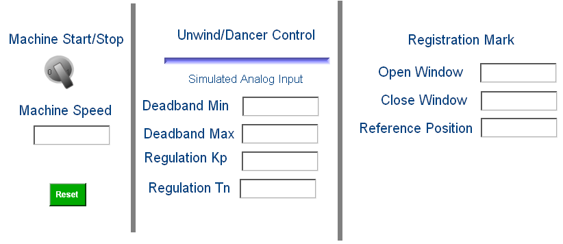
The unwind axis is geared to the virtual master axis. As the product is being unwound from the parent roll a dancer roll is monitoring the desired tension. If the tension is outside the desired adjustable dead band the gear ratio between the virtual master axis and unwind is adjusted to maintain the desired tension. The tension (Regulation Tn), gain to control the tension (Regulation Kp), minimum and maximum dead band (Deadband Min & Deadband Max) is entered on the control panel.

Figure 8-260: Unwind Base Profile
Registration Mark Control Axis
The registration mark control axis monitors the registration marks on the product and adjusts the product based on the registration mark parameters, Open Window, Close Window, and Reference Position entered on the operator panel. If the registration mark is detected between the Open Window and Close Window the registration mark is considered a good mark and the Reference Position value will be used to calculate the necessary adjustment. If the registration mark is detected outside the Open Window and Close Window values then the registration mark is ignored. Adjustments are not made during the cutting process to avoid destroying product.
Cutting Knife Axis
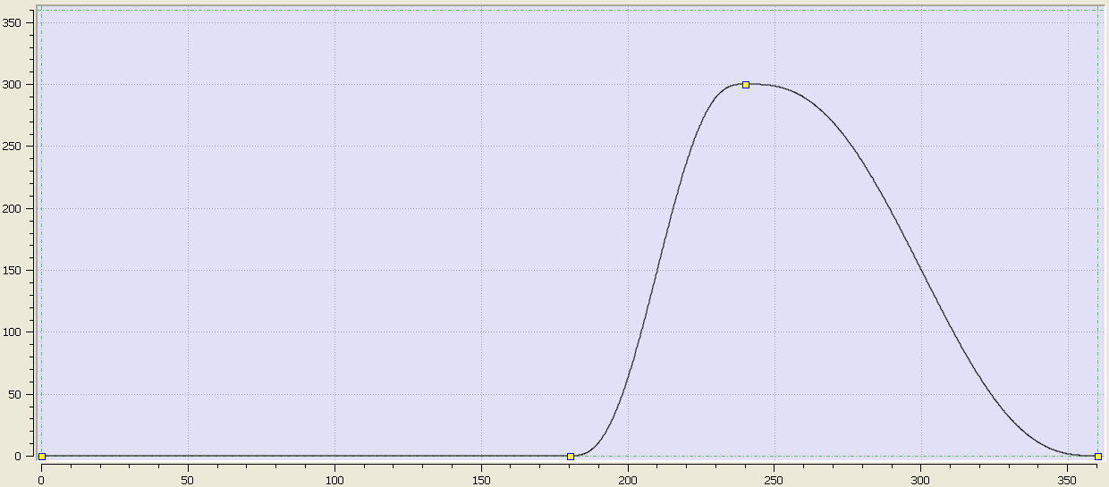
The cutting knife axis is geared to the master virtual axis based on a profile (CutKnife). The profile will start at the starting position of the virtual axis.

Figure 8-261: Cutting Knife Base Profile
PLC Program Code
| Name | How Used |
|---|---|
|
MC_GearIn |
Gears one axis to another |
|
MC_CamIn |
Gears one axis to another using a cam profile |
|
MC_TouchProbe |
|
|
MC_MoveVelocity |
Moves a single axis at a specified velocity |
|
MC_MoveSuperimp |
Relative single axis move superimposed on an active move |
|
FIFO |
Manages first in/first out list |
Table 8-54: Key Function Blocks and Kollmorgen UDFBs used in the Index-Stop application module
The main section of the PLC![]() "Programmable Logic Controller"
A Programmable Logic Controller, PLC, or Programmable Controller is a digital computer used for automation of industrial processes, such as control of machinery on factory assembly lines.
Used to synchronize the flow of inputs from (physical) sensors and events with the flow of outputs to actuators and events code contains several If/Then statements. The program sets up gearing and cam profiles for the slave axis to a virtual master. The virtual master controls the machine speed. The slave axes are manipulated by either changing the operator panel inputs or profiles. The program is monitoring registration marks on the product and making correction to the product position based on the entries at the operator panel.
"Programmable Logic Controller"
A Programmable Logic Controller, PLC, or Programmable Controller is a digital computer used for automation of industrial processes, such as control of machinery on factory assembly lines.
Used to synchronize the flow of inputs from (physical) sensors and events with the flow of outputs to actuators and events code contains several If/Then statements. The program sets up gearing and cam profiles for the slave axis to a virtual master. The virtual master controls the machine speed. The slave axes are manipulated by either changing the operator panel inputs or profiles. The program is monitoring registration marks on the product and making correction to the product position based on the entries at the operator panel.
(* The following section of code gears the Unwind axis to the Virtualmaster2 axis and synchronizes the Virtualmaster2, RegAdjust, and Cutknife axes with the respective profiles ProfileIDUnwind and ProfileIDCutKnife. *)
CASE StepCounter OF
0:
Inst_MC_GearIn( TRUE, VirtualMaster2, Unwind, 1, 1, 10000, 10000, 0, 0 );
Inst_MC_CamIn( TRUE, VirtualMaster, VirtualMaster2, 0, 0, 360, 360, 0, ProfileIDUnwind, 0 );
Inst_MC_CamIn1( TRUE, VirtualMaster, RegAdjust, 0, 0, 360, 360, 0, ProfileIDUnwind, 0 );
Inst_MC_CamIn2( TRUE, VirtualMaster, CutKnife, 0, 0, 360, 360, 0, ProfileIDCutKnife, 0 );
(* The following section of code checks that the unwind axis is geared to the Virtualmaster2 axis and that the Virtualmaster2, RegAdjust, and Cutknife axes are synchronized with the respective profiles ProfileIDUnwind and ProfileIDCutKnife. If the axes are geared and synchronized and the machine start button is selected the master axis will be run at the desired velocity. *)
IF Inst_MC_GearIn.InGear AND Inst_MC_CamIn.InSync AND Inst_MC_CamIn1.InSync AND Inst_MC_CamIn2.InSync THEN
StepCounter := 1;
END_IF;
1:
IF MachineStart THEN
IF MasterVelocity <> OldMasterVelocity THEN
Inst_MC_MoveVelocity2( FALSE, VirtualMaster, MasterVelocity, 10000, 10000, 0, 0, 0 );
Inst_MC_MoveVelocity2( TRUE, VirtualMaster, MasterVelocity, 10000, 10000, 0, 0, 0 );
OldMasterVelocity := MasterVelocity;
END_IF;
ELSE
OldMasterVelocity := 0;
END_IF;
(*********
Unwind Axis with Dancer Control
Monitor Dancer and change Gear Ratio between VirtualMaster and Unwind Axis to maintain desired tension
May also want to change gear ratio as the radius of feed material decreases due to web being used
Dancer range 0-10V, 5V mid, adjustable deadband, > deadband increase speed, < deadband decrease speed
*********)
IF MachineStart THEN
Inst_DancerUnwindGear( TRUE, DancerAnalogSignal, Kp, Tn, DeadBandMin, DeadBandMax, CycleTime );
IF Inst_DancerUnwindGear.obOutsideDeadband THEN
Inst_MC_GearIn( FALSE, VirtualMaster2, Unwind, any_to_dint((Inst_DancerUnwindGear.oUnwindGearRatio + 1)*10000000), 10000000, 10000, 10000, 0, 0 );
Inst_MC_GearIn( TRUE, VirtualMaster2, Unwind, any_to_dint((Inst_DancerUnwindGear.oUnwindGearRatio + 1)*10000000), 10000000, 10000, 10000, 0, 0 );
END_IF;
END_IF;
//Registration Mark Control Axis
//Monitor registration marks and make adjustments to RegAdjust Axis
Inst_MC_TouchProbe( TRUE, RegAdjust, TriggerRef, FALSE, 0, 0 );
IF Inst_MC_TouchProbe.Done THEN
RegistrationMarkPos := Inst_MC_TouchProbe.RecordedPosition;
Inst_MC_TouchProbe( FALSE, RegAdjust, TriggerRef, FALSE, 0, 0 );
Inst_MC_TouchProbe( TRUE, RegAdjust, TriggerRef, FALSE, 0, 0 );//Rearm for next registration mark
IF RegistrationMarkPos > OpenWindowPos AND RegistrationMarkPos < CloseWindowPos THEN //Check if mark was within good window
IF RegistrationMarkPos < ReferencePos THEN //Check if phase forward or backward is required
NewAdjustment := ReferencePos-RegistrationMarkPos;
ELSE
NewAdjustment := ReferencePos-RegistrationMarkPos;
END_IF;
Inst_FIFO( FALSE, FALSE, FALSE, NewAdjustment, Adjustment, AdjustmentArray );
Inst_FIFO( TRUE, FALSE, FALSE, NewAdjustment, Adjustment, AdjustmentArray );
IF Inst_FIFO.Count = 4 THEN
Inst_FIFO( FALSE, FALSE, FALSE, NewAdjustment, Adjustment, AdjustmentArray );
Inst_FIFO( FALSE, TRUE, FALSE, NewAdjustment, Adjustment, AdjustmentArray );
NewMarkHit := TRUE;
END_IF;
END_IF;
END_IF;
IF NewMarkHit AND ActPosVirtualMaster > 0 AND ActPosVirtualMaster < 45 THEN //Do not make adjustment during sealing process
Inst_MC_MoveSuperimp( FALSE, RegAdjust, Adjustment, MasterVelocity*3, 10000, 10000, 0, 0 );
Inst_MC_MoveSuperimp( TRUE, RegAdjust, Adjustment, MasterVelocity*3, 10000, 10000, 0, 0 );
NewMarkHit := FALSE;
END_IF;
//CutKnife
END_CASE;
Operator Panel
The Kollmorgen Automation Suite (KAS) program for this application module has an internal operator panel. The operator panel is used to set the desired values for each product and to start and stop the machine. The specific entries are described in the axis sections above. Below is a screen print of the operator panel.


