Rotary Knife Example with PLCopen
Introduction
This Rotary Knife PLCopen![]() A vendor -and product- independent worldwide association active in Industrial Control and aiming at standardizing PLC file formats based on XML Application Module details sample Pipenetwork PLC
A vendor -and product- independent worldwide association active in Industrial Control and aiming at standardizing PLC file formats based on XML Application Module details sample Pipenetwork PLC![]() "Programmable Logic Controller"
A Programmable Logic Controller, PLC, or Programmable Controller is a digital computer used for automation of industrial processes, such as control of machinery on factory assembly lines.
Used to synchronize the flow of inputs from (physical) sensors and events with the flow of outputs to actuators and events Code that controls two axes, a Feeder that moves material which has a sensor
"Programmable Logic Controller"
A Programmable Logic Controller, PLC, or Programmable Controller is a digital computer used for automation of industrial processes, such as control of machinery on factory assembly lines.
Used to synchronize the flow of inputs from (physical) sensors and events with the flow of outputs to actuators and events Code that controls two axes, a Feeder that moves material which has a sensor![]() A sensor is a type of transducer that converts one type of energy into another for various purposes including measurement or information transfer connected to a fast input
A sensor is a type of transducer that converts one type of energy into another for various purposes including measurement or information transfer connected to a fast input![]() The inputs are taken into account at each cycle depending on the system periodicity (for example each millisecond). Under certain circumstances this can be insufficient when more accuracy is needed, or if a quick response is required from the system. To fill the gap, a drive may have some Fast Input connections (generally one or two). When an event happens that triggers a Fast Input (e.g. when a sensor sends a rising edge), the detection of a signal occurs faster (which can be 1000 times more accurate than the system periodicity). Then the timestamp associated with this input can be provided to the IPC to take corrective action to capture registration marks, and a rotary knife that will match linear speeds with the Feeder axis to cut the web of material. A CAM profiles is used with the Rotary Knife to make sure that linear speeds are matched while cutting, and that the knife slows down or speeds up to sync with the web due to its circumference being different than the desired distance between cuts. With the feeder axis, a superimposed move of constantly changing amplitude is used to make adjustments due to positions of registration marks to ensure that the knife is lining up with the material at the exact desired position.
The inputs are taken into account at each cycle depending on the system periodicity (for example each millisecond). Under certain circumstances this can be insufficient when more accuracy is needed, or if a quick response is required from the system. To fill the gap, a drive may have some Fast Input connections (generally one or two). When an event happens that triggers a Fast Input (e.g. when a sensor sends a rising edge), the detection of a signal occurs faster (which can be 1000 times more accurate than the system periodicity). Then the timestamp associated with this input can be provided to the IPC to take corrective action to capture registration marks, and a rotary knife that will match linear speeds with the Feeder axis to cut the web of material. A CAM profiles is used with the Rotary Knife to make sure that linear speeds are matched while cutting, and that the knife slows down or speeds up to sync with the web due to its circumference being different than the desired distance between cuts. With the feeder axis, a superimposed move of constantly changing amplitude is used to make adjustments due to positions of registration marks to ensure that the knife is lining up with the material at the exact desired position.

The PLC code can easily be modified for use in a variety of Flying Knife applications, by modifying the CAM Profiles and Machine Cycle times to fit machines with varying mechanics and desired material cut lengths.
Axis Descriptions
Virtual Master Axis
The Axes are synchronized by using a common Virtual Master to command synchronized motion. The Master is set in modulo mode so that each period corresponds to the expected distance between knife cuts.

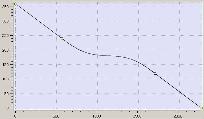
Figure 8-264: Knife CAM profile
Knife Axis
ProfileKnife CAM Profile is used to control the speed of the Knife Axis. The Profile has an input amplitude equal to the period of the Master, but an output amplitude of 360 degs to ensure that knife makes one rotation for each section of material that needs to be cut. The shape of the CAM profile guarantees a constant velocity while in the cut window so the linear material feed and rotational Knife speeds are synched while a cut is being made. Outside of the cut window the shape of the CAM will speed up or slow down the Knife depending on its diameter in respect to the distance between material cuts. If the knife circumference is larger than the distance between cuts, it will need to be speed up while not cutting, and if the knife is smaller than the cut distance it will slow down outside of the cut window. Notice for this example how the output is from 0 to 360 deg for one rotation of the knife for each period of the Master, and the velocity slows almost to a stop while not in the cut window.
Feeder Axis
The Feeder Axis is first directly geared to the Virtual Master Axis so the web of material is constantly fed through the machine. Some slipping may occur with the material in the Feeder Axis, thus registration marks will be checked. The MC_TouchProbe function captures the location of the Virtual Master Axis whenever a registration mark is seen. An adjustment distance is calculated and added in parallel to the main geared connection to the Virtual Master with the MC_MoveSuperimp function, and is used to adjust the speed of the Feed Axis while the Knife is outside of the cut window. This will either momentarily speed up if the material is behind or slow down if the feeder axis is ahead of its required position to cut the material at the correct position.
Additionally, the MC_ReadActPos function is used to check the Virtual Master position before calling the MC_MoveSuperimp function to make an adjustment move based on a registration mark. Monitoring the Virtual Master position ensures that we do not make an adjustment move while a cut is being made, when we require a constant synchronized velocity with the Knife Axis.
PLC Program Code
Key Function![]() A function calculates a result according to the current value of its inputs. A function has no internal data and is not linked to declared instances. Blocks and Kollmorgen UDFBs used in the application
A function calculates a result according to the current value of its inputs. A function has no internal data and is not linked to declared instances. Blocks and Kollmorgen UDFBs used in the application
| Name | How Used |
|---|---|
|
MC_CamTblSelect |
Converts CAM Profile to CAM Table for use with MC_CamIn function |
|
MC_CamIn |
Start CAM Relationship between Master and Slave axes with selected Profile |
|
MC_GearIn |
Start a Gear Relationship between Master and Slave axes with a specified ratio |
|
MC_MoveVelocity |
Command velocity move with Virtual Master that starts both Feeder and Knife axes |
|
MC_TouchProbe |
Checks drive fast input that monitors registration marks, latches position of virtual master when triggered |
|
MC_MoveSuperimp |
Commands relative move on the Feeder axis that acts in addition to the Gear relationship with the Virtual Master to make adjustments |
After some setup code to start CAM and Gear relationships between the machine axes and the Virtual Master, the main section of PLC Code run during the Automatic mode of the Rotary Knife Module Execution is contained in two small If/Then conditions.
The first section of setup code initializes the Knife CAM Profile, the TouchProbe that monitors registration marks, and the Feeder Gear relationship.
Inst_MC_CamTblSelect( TRUE, 'ProfileWeb', TRUE, FALSE, FALSE );
KnifeCamID := Inst_MC_CamTblSelect.CamTableID;
TrigRef.DIRECTION := 1; //Rising Edge![]() A rising edge is the transition of a digital signal from low to high. It is also called positive edge
A rising edge is the transition of a digital signal from low to high. It is also called positive edge
TrigRef.TRIGID := 1; //Axis number of capture engine(Feeder)
Inst_MC_TouchProbe( FALSE, VirtualMaster, TrigRef, FALSE, 0, 0 );
Inst_MC_TouchProbe( TRUE, VirtualMaster, TrigRef, FALSE, 0, 0 );
Inst_MC_CamIn( FALSE, VirtualMaster, KnifeAxis, 0, 0, 2266, 360, 0, KnifeCamID, 0 );
Inst_MC_CamIn( TRUE, VirtualMaster, KnifeAxis, 0, 0, 2266, 360, 0, KnifeCamID, 0 );
Inst_MC_GearIn( FALSE, VirtualMaster, FeederAxis, 1, 1, 10000, 10000, 0, 0 );
Inst_MC_GearIn( TRUE, VirtualMaster, FeederAxis, 1, 1, 10000, 10000, 0, 0 );
The second section of code executes each EtherCAT![]() EtherCAT is an open, high-performance Ethernet-based fieldbus system. The development goal of EtherCAT was to apply Ethernet to automation applications which require short data update times (also called cycle times) with low communication jitter (for synchronization purposes) and low hardware costs cycle while the Rotary Knife is running. The first line of code monitors the Start Master button that starts a velocity move with the Virtual Master.
EtherCAT is an open, high-performance Ethernet-based fieldbus system. The development goal of EtherCAT was to apply Ethernet to automation applications which require short data update times (also called cycle times) with low communication jitter (for synchronization purposes) and low hardware costs cycle while the Rotary Knife is running. The first line of code monitors the Start Master button that starts a velocity move with the Virtual Master.
The next section monitors registration marks, and when one is monitored it captures the latched position of the virtual master and compares it with the desired position to cut the material at the desired location. The required position adjustment is calculated depending on if the material needs to be sped up or slowed down to resynchronize with the Knife Axis. The TouchProbe instance monitoring the registration marks is also reset to monitor the next mark.
The last section of code waits for the Virtual Master to pass a specific reference position, 500, signifying that it is safe to start a Super Imposed adjustment move that will not interfere with a knife cut.
//Command velocity move to virtual master, starts Rotary Knife
MoveVelocityInst( StartMaster, VirtualMaster, MasterVelocity, 10000, 10000, 0, 0, 0 );
//Wait for Registration mark, set amplitude of adjustment move
Inst_MC_TouchProbe( TRUE, VirtualMaster, TrigRef, FALSE, 0, 0 );
IF Inst_MC_TouchProbe.Done THEN
LatchedPosition := Inst_MC_TouchProbe.RecordedPosition;
Inst_MC_TouchProbe( FALSE, VirtualMaster, TrigRef, FALSE, 0, 0 );
IF LatchedPosition >= 1133 THEN
Adjustment := -(2266-LatchedPosition) ; //Web needs to slow down if ahead of expected point
ELSE
Adjustment := + LatchedPosition ; //Web needs to speed up if its behind expected point
END_IF;
Count += 1; //Increment registration mark counter
END_IF;
//Checks if Rotary Knife Axis Passes reference position, make superimposed adjustment move
IF Inst_r_trig( MasterPosition > 500 ) THEN
//Reset Phase adjust to have offset ratio to make required adjustment
Inst_MC_MoveSuperimp( TRUE, FeederAxis, Adjustment, VelocityDiff, Accel, Accel, 0, 0 );
ELSE
//Reset function to be ready to enable next master cycle
Inst_MC_MoveSuperimp( FALSE, FeederAxis, Adjustment, VelocityDiff, Accel, Accel, 0, 0 );
END_IF;
Control Panel

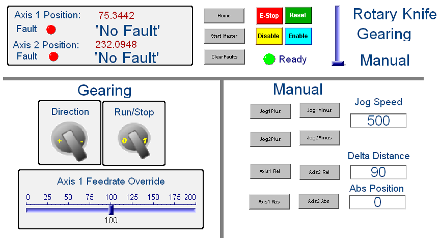
The KAS Program included in this Application Module has an internal control panel pictured above. The program starts off in the Manual state, where both Axes are disabled. The top section of the control panel works for all three machine states, allowing the Axes to be enabled, disabled, reset errors, E-stopped, or homed. The positions of each axis and fault conditions are constantly reported to the user.
Manual mode lets the user jog each axis at a specified velocity, make relative, and make absolute moves. Gearing mode starts a gearing relationship between the two Axes, and is similar to what is contained in the standard PLCopen KAS Template program. Rotary Knife mode lets the user run the previously described PLC code continuously by pressing the Start Master button.


