Configuration
The I/Os of the Profinet network must be connected to the variables via a Profinet IO controller. Start the declaration of a Profinet controller with:
- Insert > Insert Master/Port.
The following window opens.
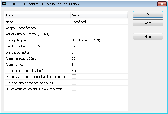
These parameter can be changed:
Parameter Meaning Name
- A device name can consists of labels and must follow these conventions:
- 1 or more labels, separated by [.]
- Total length is 1 to 240
- Label length is 1 to 63
- Labels consist of [a...z0...9-]
- Labels do not start with [-]
- Labels do not end with [-]
- The first label does not start with "port-xyz" or "port-xyz-abcde" with a,b,c,d,e, x, y, z = 0...9
- Device names do not have the form n.n.n.n, n = 0...999
- Labels do only start with 'xn-' if RFC 3490 is applied
Adapter identification
MAC address
 A Media Access Control address (MAC address) is a quasi-unique identifier assigned to most network adapters or network interface cards (NICs) by the manufacturer for identification. If assigned by the manufacturer, a MAC address usually encodes the manufacturer's registered identification number of the Profinet IO controller or name of the network connection (Windows XP or younger and Windows CE 4.1 or younger). This must be set to
 tsec0.Activity timeout factor [100ms]
Timeout for the connection establishment to the devices (maximum time between beginning of connection establishment and the first cyclic data exchange); Timeout factor based on 100ms.
Priority Tagging
Yes: cyclic data exchange without priority tag.
No: data exchange with priority tag.Send clock factor [31,250µs]
Send clock factor. Multiple of 31,250µs (32 = 1ms).
Watchdog factor
Watchdog factor (default 3):
The Watchdog factor defines how many frames may be missing until the device is set back. Watchdog triggers:
a) frames may be lost; e.g. due to bad cabling.
b) frames may arrive delayed due to blocking situations in the network; e.g. due to a non-separated network.The watchdog may be triggered as soon as HTTP file transfer occurs between the AKD PDMM or PCMM and the IDE
 "Integrated development environment"
An integrated development environment is a type of computer software that assists computer programmers in developing software.
IDEs normally consist of a source code editor, a compiler and/or interpreter, build-automation tools, and a debugger when the default value is used. Increase this value if you encounter frequent watchdog triggers.
 Alarm timeout [100ms]
Alarm timeout (default 50).
Alarm retries
Number of alarm retries (default 3).
IP configuration delay [ms]
IP configuration delay (default 500):
Defines the time to wait whether some devices are not ready after start.Do not wait until connect hat been competed
On: the application starts immediately.Off: the application starts after all devices are connected.Start despite disconnected slaves
On: the application starts despite configured but not found devices.Off: the application starts if all configured devices were found only.I/O communication only from within cycle On: Run I/O communication from within VM-cycleOff: Run I/O communication outside VM-cycle. - Mark the controller and click Insert > Insert Slave/Datablock to add a Profinet IO device.
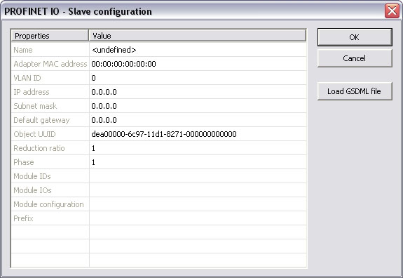
These parameter can be changed:
Parameter Meaning Name
- A device name can consists of labels and must follow these conventions:
- 1 or more labels, separated by [.]
- Total length is 1 to 240
- Label length is 1 to 63
- Labels consist of [a...z0...9-]
- Labels do not start with [-]
- Labels do not end with [-]
- The first label does not start with "port-xyz" or "port-xyz-abcde" with a,b,c,d,e, x, y, z = 0...9
- Device names do not have the form n.n.n.n, n = 0...999
- Labels do only start with 'xn-' if RFC 3490 is applied
Adapter MAC address
MAC address of the Profinet IO device
Virtual LAN ID
IP address
IP address of the device
Subnet mask
Subnet mask for the IP address of the device
Default gateway
Default gateway
Object UUID
UUID of the device
Reduction ratio
Reduction ratio (default 16):
The Reduction ratio defines the frequency for data to be exchanged with the device. The transfer rate is calculated by <Send clock factor> * 31,250 µs * <Reduction ratio>. The Send clock factor is a master parameter with a default value of 32 (all known devices work with this Send clock factor).
With the default setting of 16 the data transfer rate is 48ms; for 2 it is 2ms...;
Most devices support Reduction ratio settings of 1,2,4,8,16,32...Phase
Phase
Module IDs
Module IDs of the device modules.
Module IOs
Module IOs of the device modules.
Module configuration
Module configuration.
Prefix
Prefix for the variables.
With the calculation of <Watchdog factor> * <Reduction ratio> * <Send clock factor> * 31,250 µs you get the time that may expire between two frames until the device is set back. I.e. for the default settings 3 * 32 * 31,250 µs the connection will be set back after 3ms of missing frames. For office networks this time is rather low. It is recommended to us a Reduction ratio of 32 and a Watchdog factor of 24 for such networks. I.e. the connection will be reset after 24 * 32 * 32 * 31,250 µs = 768 ms. If this data exchange rate is to low please separate the PROFINET IO network from the office network (e.g. by a router).
- Click
Load GSDML fileto import the necessary GSDML file.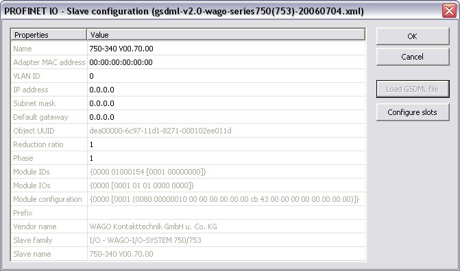
- Do the slot configuration after the GSDML file import.
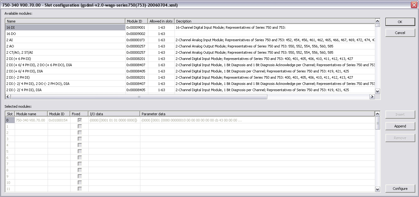
- Select the modules in the upper list. With the buttons
InsertandAppendthe modules are copied to the lower list.You can not configure each module. Only modules with some sub modules respectively with a sub module with parameter data can be configured. Mark the according module in the lower list and click the
Configurebutton.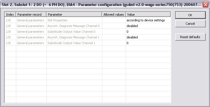
- Now you can connect the variables with the I/Os. Use Insert > Insert/Set Variable in order to append a variable to a device.
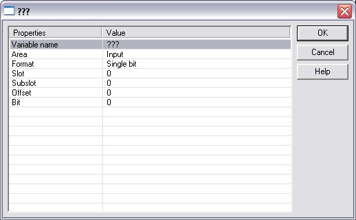
These parameter can be changed:
Parameter Description Variable name
Variable name following the IEC
 "International Electrotechnical Commission"
IEC is a not-for-profit, non-governmental international standards organization that prepares and publishes International Standards for all electrical, electronic and related technologies 61131-3 syntax.
"International Electrotechnical Commission"
IEC is a not-for-profit, non-governmental international standards organization that prepares and publishes International Standards for all electrical, electronic and related technologies 61131-3 syntax.Area
Output, Output IOCS, Output IOPS, Input, Input IOCS, Input IOPS, device status, or PNIO status.
Format
32 bit float, Signed 16 bit integer, Signed 32 bit integer, Signed 8 bit integer, Single bit, Unsigned 16 bit integer, Unsigned 32 bit integer, Unsigned 8 bit integer.
Slot
Slot Number
Subslot
Subslot Number
Offset
Offset
Bit
Bit
The offset of a variable is relative to a sub module. Thus also depending from a slot and subslot. The offset of the first variable of a sub module is always 0.
- All settings can be changed in the grid too. The information show refers to the items below of the selected item in the configuration tree.
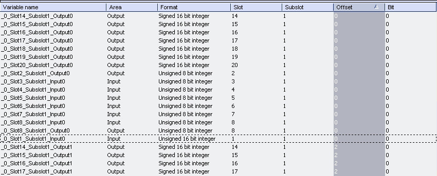
If the GUI
 "Graphical User Interface"
A GUI is a type of user interface which allows people to interact with a computer and computer-controlled devices Views is online with a target system the grid shows the real-time data of the variables.
"Graphical User Interface"
A GUI is a type of user interface which allows people to interact with a computer and computer-controlled devices Views is online with a target system the grid shows the real-time data of the variables.The Profinet maximum data size is 1440 bytes Input length and 1440 bytes Output length. To calculate the size, use the slot configuration view to count the number of bits per slot and convert to bytes. For example, 7 slots containing 16 outputs of 32 bits each, would be 7 * 16 * 32 = 3584 bits = 448 bytes.


