AKT2G-SM-L50 General Connection Examples
-
-
Risk of injury through electric shock and damage to the device!
Bring the Bus Terminal system into a safe, de-energized state before starting mounting, disassembly or wiring of the Bus Terminals.
-
-
Connect the motor strands correctly!
Connect the windings of a motor strand only to the terminal points of the same output driver of the stepper motor terminal, e.g.:
- one motor strand to terminal points A1 and A2,
- the other motor strand to terminal points B1 and B2.
Connecting a motor strand to the terminal points of different output drivers (e.g. to A1 and B1) can lead to destruction of the output drivers of stepper motor terminal!
-
-
Use a brake chopper terminal (Global search and replace: AKT2G-BRC-000-000) for short deceleration ramps!
Very short deceleration ramps may lead to temporarily increased feedback. In this case the terminal would report an error. In order to avoid this, a brake chopper terminal AKT2G-BRC-000-000 should be connected in parallel to the power supply for the motor so that any energy being fed back is absorbed.
-
-
Fuse protection of the supply voltage
The electrical protection of the load voltage must be selected in such a way that the maximum flowing current is limited to 3 times the rated current (max. 1 second)!
Connection types
The AKT2G-SM-L50 Stepper Motor terminal has bipolar output stages and can control bipolar and unipolar motors.
Bipolar motors
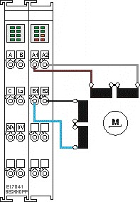
|
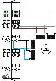
|
Unipolar Motors
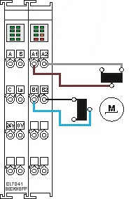
Figure 8-55: Bipolar control with only one half of each winding is controlled
Encoder
Connecting an encoder (24 V)
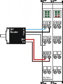
Figure 8-56: The encoder is supplied from the power contacts via terminal points 3 (+24 V) and 7 (0 V).


