Standard Mode
Stepper motors were originally operated with very simple output stages, which were only able to switch the voltage of the motor phases separately (nowadays current control takes place via PWM with pulse-width modulation as standard). Initially the motor phases there were controlled individually in turn. A switching sequence in the positive direction of rotation corresponds to the switching sequence (+A, +B, -A, -B). Sequential switching results in rather irregular operation in this mode. In order to make the operation smoother, so-called microstepping was introduced later, in which the four set voltages were extended by intermediate values (e.g. from a stored sine table). These days, microstepping based on 64 steps is commonly used.
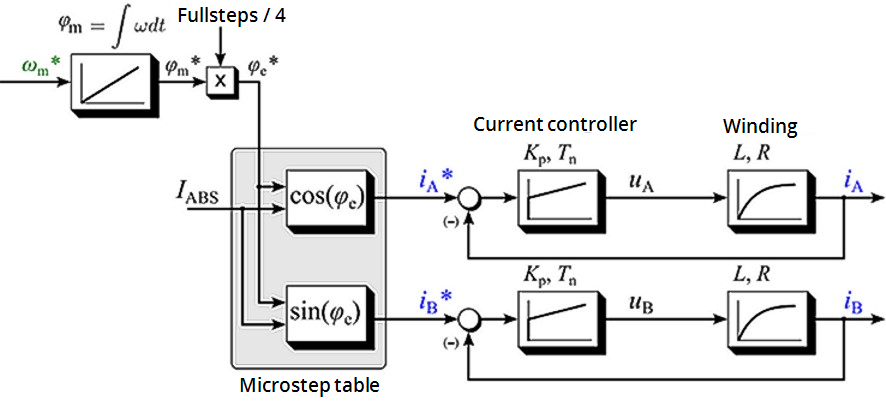
Figure 7-296: Control structure of a standard stepper motor drive
Neglecting the sampling resulting from the microstepping, the motor current I as function of the electrical angle φe and of the magnitude of the motor current IABS (when using a current controller) can be described as follows:
I(φe) = IA + jIB = IABScos(φe) + jIABSsin(φe)
Represented by magnitude and angle:
I(φe) = IABS · ejφe
It follows that a rotation of the electrical angle φe is equivalent to four full steps. (A stepper motor with 200 full steps therefore has 50 pole pairs).
The shaft aligns itself if a constant current is set with no load at the motor shaft. Within a pole pairs the shaft points in the direction of the active stator field.
If an external load is applied to the motor shaft, the shaft is turned out of the field direction, resulting in a load angle (also referred to as angular displacement) (relative to an electric rotation of the angle φe). The load angle depends on the design of the stepper motor itself, the motor current and the torque![]() Torque is the tendency of a force to rotate an object about an axis. Just as a force is a push or a pull, a torque can be thought of as a twist acting on the shaft. The relationship is non-linear!
Torque is the tendency of a force to rotate an object about an axis. Just as a force is a push or a pull, a torque can be thought of as a twist acting on the shaft. The relationship is non-linear!
If the load angle exceeds a motor-dependent maximum value (i.e. if the maximum machine torque under these boundary conditions is exceeded), the load torque can no longer be maintained by the motor. If the shaft is turned further out of the rotary field, it "tips", resulting in one or more step losses. The "tip angle" may vary between motor types. Often, it lies between around 45° and 65°.
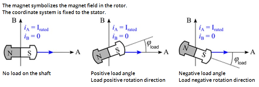
Figure 7-297: Behavior of the rotor under load
The load angle is of interest for the user, because it allows conclusions about the load on the shaft. It is measured by evaluating the induced countervoltage* and can be used to epitomize the drive system.


