 FB_FirstOrderDigitalFilter
Description
This FB is defined to filter an Analog signal.
In any control system with an analog feedback signal present there is the risk of unwanted noise and jitter that can compromise the signal integrity yielding a less the desirable system.
This Kollmorgen UDFB![]() "User Defined Function Block"
UDFB can be used as a sub-function block in another program of the application. It is described using FBD, LD, ST or IL language. Input / output parameters of a UDFB (as well as private variables) are declared in the variable editor as local variables of the UDFB will provide a digital first order filter of an analog feedback signal from an LVDT, tension transducer, potentiometer, encoder, resolver, or some other like device. The amount of filtering is based on a gain value and can provide no filter to full filter conditioning.
"User Defined Function Block"
UDFB can be used as a sub-function block in another program of the application. It is described using FBD, LD, ST or IL language. Input / output parameters of a UDFB (as well as private variables) are declared in the variable editor as local variables of the UDFB will provide a digital first order filter of an analog feedback signal from an LVDT, tension transducer, potentiometer, encoder, resolver, or some other like device. The amount of filtering is based on a gain value and can provide no filter to full filter conditioning.
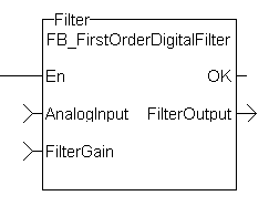
The following figure shows the function block I/O

Figure 7-225: CBS First Order Digital Filter
Arguments
Inputs
|
EN |
Description |
Enables execution (FFLD only ) |
|
Data type |
BOOL |
|
|
Range |
— |
|
|
Unit |
N/A |
|
|
Default |
|
|
|
AnalogInput |
Description |
Analog Input from transducer |
|
Data type |
INT |
|
|
Range |
— |
|
|
Unit |
N/A |
|
|
Default |
|
|
|
FilterGain |
Description |
Filter Gain |
|
Data type |
REAL |
|
|
Range |
[1 - 0.05] |
|
|
Unit |
N/A |
|
|
Default |
— |
Outputs
|
OK |
Description |
Execution Complete |
|
Data type |
BOOL |
|
|
Range |
[0,1] |
|
|
Unit |
|
|
|
FilterOutput |
Description |
Filtered analog input value |
|
Data type |
REAL |
|
|
Range |
[0,1] |
|
|
Unit |
|
Usage
When using this UDFB, the Enable (EN) input should always be energized in order to provide the desired filtering.
- The AnalogInput input is the unfiltered “raw” analog feedback signal from an LVDT, tension transducer, potentiometer, or some other like device.
- The FilterGain defines the amount of filtering to be used. The range of the gain is from 1.0 or no filtering to 0.05 or the maximum filtering.
- The FilterOutput is the filtered analog input and is typically used as an input to some other function block or UDFB that has an analog input, for example the MCFB_GearedWebTension UDFB.
- The implementation of the digital first order filter is for PLCopen
 A vendor -and product- independent worldwide association active in Industrial Control and aiming at standardizing PLC file formats based on XML.
 - The equation is defined as:
Input*Gain+Output*(1-Gain) = Output - The steady state filter delay with a gain of 0.8 can be seen in the following table.
| FilterGain | FilterInput | FilterOutput |
|---|---|---|
|
0.8 |
0 |
0 |
|
100 |
80 |
|
|
100 |
96 |
|
|
100 |
99.2 |
|
|
100 |
99.84 |
|
|
100 |
99.968 |
|
|
100 |
99.9936 |
|
|
100 |
99.99872 |
|
|
100 |
99.999744 |
|
|
100 |
99.9999488 |
|
|
100 |
99.99998976 |
|
|
100 |
99.99999795 |
|
|
100 |
99.99999959 |
|
|
100 |
99.99999992 |
|
|
100 |
99.99999998 |
|
|
100 |
100 |
|
|
100 |
100 |
|
|
100 |
100 |
|
|
100 |
100 |
|
|
100 |
100 |
|
|
100 |
100 |
|
|
100 |
100 |
|
|
100 |
100 |
Table 7-51: Filter Input Delay Example
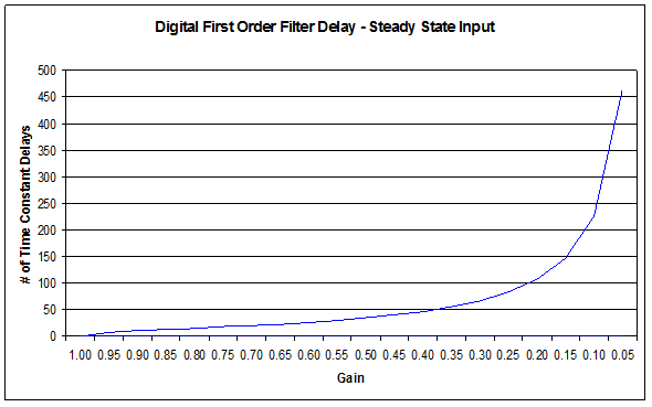
The range of the filter gain is between 1.00 and 0.05. From the table, for a filter gain of 0.8 there is a delay of 15 time constants with a time constant defined as the rate the UDFB is scanned or executed in the application. For example if the UDFB was executed every millisecond a gain of 0.8 would provide a filter delay of 15ms. Conversely a gain of 1.00 provides zero filtering and the output signal follows the input signal, and a gain of 0.05 provides the most filtering for 463 ms.
The numbers of filter delays for a steady state analog input at a given gain are shown in the table and graph below.
| Gain |
Filter Delay Tn |
|---|---|
|
1.00 |
0 |
|
0.95 |
8 |
|
.90 |
11 |
|
.85 |
13 |
|
.80 |
15 |
|
.75 |
18 |
|
.70 |
20 |
|
.65 |
23 |
|
.60 |
26 |
|
.55 |
30 |
|
.50 |
35 |
|
.45 |
40 |
|
.40 |
47 |
|
.35 |
56 |
|
.30 |
66 |
|
.25 |
83 |
|
.20 |
107 |
|
.15 |
146 |
|
.10 |
226 |
|
.05 |
463 |

Of course a real world analog input is most always a varying feedback signal. In Table 2.3 this is shown with an initial input of 100, a gain of 0.8, and a random variability of 10%.Filter Input
| Filter Input | Filter Current Output | Amount of Input Filtering | Random Filter % Variation |
|---|---|---|---|
|
0 |
0 |
0 |
10% |
|
100 |
80 |
-20 |
|
|
97.38903813 |
93.9112305 |
-3.477807626 |
|
|
92.67638093 |
92.92335084 |
0.246969915 |
|
|
94.12988912 |
93.88858146 |
-0.241307655 |
|
|
103.0835564 |
101.2445614 |
-1.838994993 |
|
|
91.16845433 |
93.18367575 |
2.015221422 |
|
|
93.23936976 |
93.22823096 |
-0.011138803 |
|
|
94.90272089 |
94.56782291 |
-0.334897986 |
|
|
103.3070737 |
101.5592235 |
-1.747850153 |
|
|
96.83149418 |
97.77704005 |
0.945545867 |
|
|
96.35024002 |
96.63560002 |
0.285360007 |
|
|
99.82417525 |
99.1864602 |
-0.637715045 |
|
|
105.0792636 |
103.9007029 |
-1.178560685 |
|
|
97.36988208 |
98.67604626 |
1.306164172 |
|
|
107.82502 |
105.9952253 |
-1.829794752 |
|
|
97.7886524 |
99.42996698 |
1.641314572 |
|
|
108.2038024 |
106.4490353 |
-1.754767081 |
|
|
91.58527607 |
94.55802792 |
2.972751845 |
|
|
93.6783421 |
93.85427926 |
0.175937164 |
|
|
102.8695349 |
101.0664838 |
-1.803051129 |
|
|
93.95916817 |
95.3806313 |
1.421463121 |
|
|
108.6579707 |
106.0025028 |
-2.655467871 |
|
|
109.3425748 |
108.6745604 |
-0.668014397 |
|
|
103.9066 |
104.8601921 |
0.953592077 |
|
|
92.30112142 |
94.81293555 |
2.511814127 |
|
|
109.4460726 |
106.5194452 |
-2.926627416 |
|
|
94.88799896 |
97.21428821 |
2.326289251 |
|
|
105.4738635 |
103.8219484 |
-1.651915057 |
|
|
102.988167 |
103.1549233 |
0.166756284 |
|
|
92.92925408 |
94.97438792 |
2.045133846 |
|
|
95.58185568 |
95.46036213 |
-0.121493552 |
|
|
109.414248 |
106.6234708 |
-2.790777178 |
|
|
106.5661311 |
106.577599 |
0.011467953 |
|
|
99.85857253 |
101.2023778 |
1.343805301 |
|
|
107.865421 |
106.5328124 |
-1.332608643 |
|
|
92.19683177 |
95.0640279 |
2.867196126 |
|
|
104.8558146 |
102.8974573 |
-1.958357346 |
|
|
104.5140236 |
104.1907104 |
-0.323313268 |
|
|
104.3675014 |
104.3321432 |
-0.035358206 |
|
|
109.2704266 |
108.2827699 |
-0.987656683 |
|
|
101.4962729 |
102.8535723 |
1.35729941 |
|
|
92.19199163 |
94.32430776 |
2.132316128 |
|
|
99.13065312 |
98.16938405 |
-0.961269073 |
|
|
103.5068114 |
102.4393259 |
-1.067485466 |
|
|
109.502983 |
108.0902516 |
-1.412731426 |
|
|
99.05504822 |
100.8620889 |
1.80704068 |
|
|
94.97711299 |
96.15410817 |
1.176995182 |
|
|
107.1063597 |
104.9159094 |
-2.190450308 |
|
|
91.12245188 |
93.88114339 |
2.758691504 |
|
|
108.130314 |
105.2804799 |
-2.849834129 |
|
|
104.2923832 |
104.4900025 |
0.197619344 |
|
|
101.3775072 |
102.0000062 |
0.62249907 |
|
|
100.5303014 |
100.0399168 |
-0.490384645 |
Averages |
Table 7-52: Filter Input Lag Example - Random Input
Example
Structured Text
//Filter analog input signal with a gain of 0.8 to remove noise
FilteredOutput:= Inst_FB_FirstOrderDigitalFilter( AnalogInput1Value, 0.8 );
Ladder Diagram

Function Block Diagram

 [Top]
[Top]


