EtherCAT Devices tab
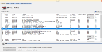
The EtherCAT![]() ***EtherCAT is an open, high-performance Ethernet-based fieldbus system. The development goal of EtherCAT was to apply Ethernet to automation applications which require short data update times (also called cycle times) with low communication jitter (for synchronization purposes) and low hardware costs Devices tab lists all the EtherCAT devices and provides for the ability to discover and map their use. The interface is slightly different for AKD and AKD2G drives. The AKD2G prompts you to select the mapping by the drive axis.
***EtherCAT is an open, high-performance Ethernet-based fieldbus system. The development goal of EtherCAT was to apply Ethernet to automation applications which require short data update times (also called cycle times) with low communication jitter (for synchronization purposes) and low hardware costs Devices tab lists all the EtherCAT devices and provides for the ability to discover and map their use. The interface is slightly different for AKD and AKD2G drives. The AKD2G prompts you to select the mapping by the drive axis.
Figure 4-104: EtherCAT Devices Summary Form
First generation AKD drives support one axis per drive, while AKD2G drives support two axes per drive. When configuring drives in the EtherCAT Devices tab, you will need to designate which motion axis applies to each "drive axis", which is the actual axis the drive controls.
| Item | Description |
|---|---|
| Show only drives | This option hides from the list all |
| Scan Devices | The KAS Runtime |
| Name, Vendor, Product, and Model | The project device name, vendor name, product name (or code number), and model number for each device is displayed and ordered by the position in the tree. The model (when available) includes the extension and connectivity options, NBEC for example. See AKD Models and AKD2G Models for information on interpreting the model text of Kollmorgen drives. |
| FW Version |
For Kollmorgen drives, the firmware version is displayed on the conditions that:
For other devices, the firmware version is displayed if the Scan Devices routine was successfully run and the device supports reading this informaiton over EtherCAT (i.e. it uses CoE object 0x100A:0). Otherwise (Unknown) is displayed.
|
| Drive Axis Number | This number designates which axis, of those available on a drive, is being defined. For most drives, this number will just be a "1", but for AKD2Gs, there are two entries, Drive Axis Number 1 and Drive Axis Number 2, |
| Mapped to Axis |
For each drive, it is displayed if it is:
|
| Simulated |
Select this option when you want to simulate the device, which means that the device is not used and no communication to this device is performed through the fieldbus. |
| Save parameters to NV memory |
Allows you to save the drives' parameters to the NVRAM of each drive currently selected in the list. This action is enabled only when the Online Mode is activated You will be automatically be prompted with the option to save modified drive parameters if this action has not been performed prior to the following circumstances.
|
| Upgrade Firmware |
This command triggers a firmware upgrade for the selected drives (you can use Ctrl+A shortcut to select all drives). For more details, refer to FAQ section. |
Scan Devices
The scan process allows the following tasks:
- Discover the devices and modules physically present in the fieldbus network (see EtherCAT Network - Physical View)
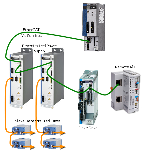
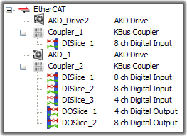
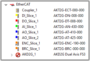
- Map them to items under the EtherCAT node of the Project Explorer (see EtherCAT Network - Logical View. K-Bus on left, E-Bus on right)
Note that the order of the devices in the tree is the same as in the real fieldbus network.

Figure 4-105: EtherCAT Network - Physical View

|

|
|
Figure 4-106: EtherCAT Network - Logical View. K-Bus on left, E-Bus on right |
|
During the scan operation, all physical devices connected to the EtherCAT network will be discovered and identified. The KAS IDE will list the devices in the order they are connected. Kollmorgen devices, which include AKD and S300![]() "Servostar 300 drive"
See Servo Drive in Glossary/S700
"Servostar 300 drive"
See Servo Drive in Glossary/S700![]() "Servostar 700 drive"
See Servo Drive in Glossary drives, Standard I/O Couplers, and remote I/O terminals (for a list, see "Remote Input/Output Terminals") will include detailed information for each device.
"Servostar 700 drive"
See Servo Drive in Glossary drives, Standard I/O Couplers, and remote I/O terminals (for a list, see "Remote Input/Output Terminals") will include detailed information for each device.
The status of devices can be determined by their icon in the logical view.
| Icon | Meaning | Description |
|---|---|---|
| (device icon) | Normal | The device has been added by scanning the system. The associated ESI file has been found. The icon varies by device, but is the icon set by the manufacturer in the ESI file. |
|
|
Excluded | The device has been added manually or has been disassociated from a discovered device. |
|
|
ESI missing | The ESI file is missing. |
|
|
Error | For AKD, shown when there is an error. |
Table 4-24: EtherCAT device icon descriptions.
Scan Limitations
- I/O slices for Standard I/O Coupler do not reveal their Device IDs.
- The discovery feature does not differentiate between AKT-DN-004-000 and AKT-DNH-004-000 I/O terminals. Nor between AKT-DN-008-000 and AKT-DNH-008-000.
- Devices other than those made by Kollmorgen will be identified by the Vendor Name (or ID number) and Product Name (or ID number). If the device is missing an ESI file, then you will need to import the ESI file supplied by the device Vendor. The ESI file is required by the IDE to decode and display the Product Name, Device Description, and other details.
- ESI files for any MDP devices connected ot the network should be added to KAS IDE's ESI library before starting a scan. If the ESI file for an MDP device is not available, then the scan cannot identify the device and cannot discover any physical or logical modules under the device.


