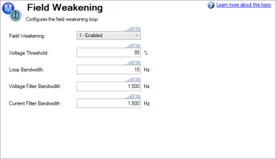
 Field Weakening View
The field weakening settings are nested under the Motor section of the View Tree. This view lets you configure the field weakening loop.
| Element | Description | Command |
|---|---|---|
| Field Weakening | This field allows a rotary permanent magnet motor to operate above rated speed. | AXIS#.MOTOR.FIELDWEAKENING |
| Voltage Threshold |
This field determines the field-weakening loop’s threshold voltage with respect to the bus voltage in [%]. By default, this value is set to 95%, meaning if the magnitude of the motor-voltage vector tries to go above 95% of bus voltage, the field weakening algorithm activates. Once activated, it maintains the motor-voltage vector magnitude at 95% of bus voltage. It applies whatever d-axis current necessary to reduce the induced back-emf-voltage of the motor to create the commanded q-axis current.
|
AXIS#.FIELDWEAKENING.VBUSMARGIN |
| Loop Bandwidth |
Thid field determines the field-weakening-loop’s bandwidth
To correctly set the internal parameters of the field weakening loop, based on the commanded bandwidth, the following motor parameters must be set correctly: |
AXIS#.FIELDWEAKENING.LOOPBW |
| Voltage Filter Bandwidth |
This field determines the bandwidth of the second order low-pass biquad filters that are applied on the q-axis and d-axis voltages for noise reduction. These voltages are used inside the field weakening algorithm for regulating the motor-voltage-vector-magnitude when operating above base speed. Lower bandwidths result in cleaner signals but can also create phase lag and lower the phase margin of the system. Depending on the required speed of the motion, they can be adjusted. |
AXIS#.FIELDWEAKENING.VOLTFILTER |
| Current Filter Bandwidth |
This field determines the bandwidth of the second order low-pass biquad filters that are applied on the q-axis and d-axis currents for noise reduction. These currents are used inside the field weakening algorithm for regulating the motor-voltage-vector-magnitude when operating above base speed. Lower bandwidths result in cleaner signals but can also create phase lag and lower the phase margin of the system. Depending on the required speed of the motion, they can be adjusted. |
AXIS#.FIELDWEAKENING.CURRFILTER |
See Field Weakening for more information.


