WorkBench Interface: View Diagrams

Views allow you to configure your device using titles such as Power, Feedback, and Electronic Gearing. Some WorkBench views are largely graphical, displaying a diagram. These diagrams allow you to enter criteria through selectable elements, and visualize the results. The following image provides a comparison of a graphical view and a conventional view.
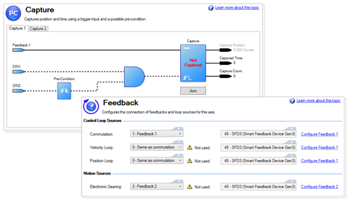
Following is a key of common elements found in these views and how they are used.

Interface Element Description
Blue Arrow This clickable item requires user input, such as selecting an input type or editing some values. The box element comes in multiple sizes.
Blue Box
Blue Circle
Black Arrow This is a read-only value, such as an output speed or a calculated position.
Solid Black Line This signifies a continuous flow of information
Dashed Black Line This signifies a triggered flow of information
Dashed Gray Line This signifies unused or inactive information
And Block This signifies a block where an AND logic calculation is performed.
Math Block This signifies a block where calculations are performed. Values which are added or subtracted are shown by the block.
Link icon The Link icon indicates a link to another place in WorkBench. Clicking the icon closes the current view and opens a new view where you may make further changes. Note that the icon seen to the left is scaled to be larger than in the interface.
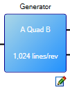
Editable icon

This icon signifies that a block is editable. Clicking the icon opens a Property Editor, where data may be set.

The Editable icon may be associated with Arrows or Boxes, as seen below.

Property Editor

The Property Editor is used by editable diagram blocks and allow you to edit one or more properties. Clicking the close icon or clicking outside of the Property Editor will set the value and close the Property Editor. If an error occurred due to the setting, the block will turn red.