Inputs
IN1 : BOOL First Boolean input
IN2 : BOOL Second Boolean input
Outputs
Q : BOOL Boolean OR of all inputs
Truth table
|
IN1 |
IN2 |
Q |
|
0 |
0 |
0 |
|
0 |
1 |
1 |
|
1 |
0 |
1 |
|
1 |
1 |
1 |
Remarks
In FBD![]() "Function block diagram"
A function block diagram describes a function between input variables and output variables. A function is described as a set of elementary blocks language, the block can have up to 16 inputs. The block is called
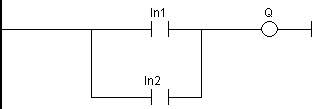
">=1" in FBD language. In FFLD language, an OR operation is represented by
contacts in parallel. In IL
"Function block diagram"
A function block diagram describes a function between input variables and output variables. A function is described as a set of elementary blocks language, the block can have up to 16 inputs. The block is called
">=1" in FBD language. In FFLD language, an OR operation is represented by
contacts in parallel. In IL![]() "Instruction list"
This is a low-level language and resembles assembly language, the OR instruction performs a logical OR between the
current result and the operand. The current result must be Boolean. The ORN instruction
performs an OR between the current result and the Boolean negation of the operand.
"Instruction list"
This is a low-level language and resembles assembly language, the OR instruction performs a logical OR between the
current result and the operand. The current result must be Boolean. The ORN instruction
performs an OR between the current result and the Boolean negation of the operand.
ST Language
Q := IN1 OR IN2;
Q := IN1 OR IN2 OR IN3;
FBD Language
(* the block can have up to 16 inputs *)

FFLD Language
(* parallel contacts *)

IL Language
Op1: FFLD IN1
OR IN2
ST Q (* Q is equal to: IN1 OR IN2 *)
Op2: FFLD IN1
ORN IN2
ST Q (* Q is equal to: IN1 OR (NOT IN2) *)
See also


