AKT2G-ENC-190-000 LEDs and Connection
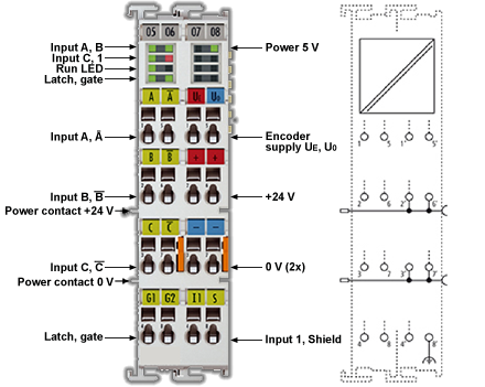
Figure 8-31: AKT2G-ENC-190-000
Connection
-
-
Encoder supply via the terminal
The encoder supply voltage (5 V), can be taken from the terminal point 1’.
| Terminal Point | No. | Comment |
|---|---|---|
| A | 1 | Encoder input A |
| B | 2 | Encoder input B |
| C | 3 | Encoder input C |
| Latch |
4 | Latch input |
| ¬A | 5 | Encoder input A |
| ¬B | 6 | Encoder input B |
| ¬C | 7 | Encoder input C |
| Gate 24 V | 8 | Gate input |
| Ue = +5 V | 1' | +5 V encoder supply |
| +24 V | 2' | +24 V (internally connected to terminal point 6' and positive power contact) |
| 0 V | 3' | 0 V (internally connected to terminal point 7' and negative power contact) |
| Input 1 | 4' | Status input 1 Alarm input from rotary encoder. Internally connected to 5 V via pull-up. Switching to negative potential, i.e. connection to GND leads to error bit and LED display. If externally supplied (not recommended) 5 V max. against GND is permitted. |
| Uo = 0 V | 5' | 0 V encoder supply |
| +24 V | 6' | +24 V (internally connected to terminal point 2' and positive power contact) |
| 0 V | 7' | 0 V (internally connected to terminal point 3' and negative power contact) |
| Shield | 8' | Screen |
LEDs
| LED | Color | Meaning | ||||||||||||||||
|---|---|---|---|---|---|---|---|---|---|---|---|---|---|---|---|---|---|---|
|
LED |
Color |
Meaning |
||||||||||||||||
|
INPUT A, B, C |
green |
indicates TRUE level |
||||||||||||||||
|
INPUT 1 |
red |
is lit, if INPUT 1 is connected to GND [INPUT 1 is connected to an internal 5 V HIGH level though internal pull-up (default)] |
||||||||||||||||
|
LATCH |
green |
is lit, if a signal (+24 V) is connected to the latch input |
||||||||||||||||
|
GATE |
green |
is lit, if a signal (+24 V) is connected to the gate input |
||||||||||||||||
|
RUN |
green |
This LED indicates the terminal's operating state:
|
||||||||||||||||
|
POWER 5 V |
green |
Operating voltage display for incremental encoder power supply |


