 MC_SetKinTra
Description
After MC_SetKinTra(...) is called, the controller will automatically calculate the inverse kinematics for the robot axes, converting the robot path motion into the individual robot joint axis trajectories. Several transform types are available for common robotic systems and are configurable with the MC_KIN_REF Structure. The parameters in the MC_KIN_REF structure define the specific robot geometry.
-
-
Description of the structure may be found in MC_KIN_REF Structure.

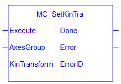
Figure 7-169: MC_SetKinTra
Arguments
See Function Blocks - General Rules for more information about how inputs and outputs work.
Input
| Execute | Description | On the rising edge |
| Data type | BOOL | |
| Range | 0, 1 | |
| Unit | N/A | |
| Default | N/A | |
| AxesGroup | Description | The axis group that will receive the axis trajectory values from the kinematic transform. |
| Data type | AXIS_GROUP_REF | |
| Range | N/A | |
| Unit | N/A | |
| Default | N/A | |
| KinTransform | Description | Kinematic robotic transform defined by the MC_KIN_REF Structure |
| Data type | MC_KIN_REF | |
| Range | N/A | |
| Unit | N/A | |
| Default | N/A |
Output
| Done | Description |
If True, then the command completed successfully. |
| Data type | BOOL | |
| Error | Description | If True, an error has occurred. |
| Data type | BOOL | |
| ErrorID | Description | Indicates the error if Error output is set to TRUE. See table in PLCopen |
| Data type | INT |
Example
Structured Text
// MC_SetKinTra ST Example

// DeltaBotTransform is of type MC_KIN_REF

DeltaBotTransform.TransformType := MC_TRANSFORM_TYPE_DELTA;
DeltaBotTransform.KinParameters[MC_DELTA_KIN_PARAM_RADIUS_BASE_LENGTH] := 10.0;
DeltaBotTransform.KinParameters[MC_DELTA_KIN_PARAM_RADIUS_END_LENGTH]  := 2.0;
DeltaBotTransform.KinParameters[MC_DELTA_KIN_PARAM_MOTOR_ARM_LENGTH]   := 5.0;
DeltaBotTransform.KinParameters[MC_DELTA_KIN_PARAM_END_ARM_LENGTH]     := 25.0;

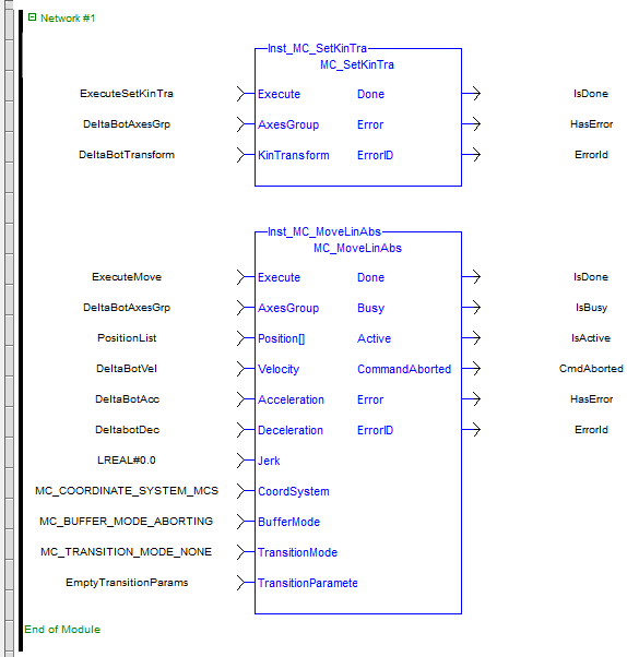
Inst_MC_SetKinTra(True, DeltaBotAxesGrp, DeltaBotTransform);

// ...

Inst_MC_MoveLinAbs(True, DeltaBotAxesGrp, PositionList, DeltaBotVel, DeltaBotAcc, DeltaBotDec, LREAL#0.0, MC_COORDINATE_SYSTEM_MCS, MC_BUFFER_MODE_ABORTING, MC_TRANSITION_MODE_NONE, EmptyTransitionParams);
Function Block Diagram

Ladder Diagram


