DIO#.TERM
Description
Sets whether the bi-directional IO is terminated or not.
| Value | Description |
|---|---|
| 0 | Not terminated |
| 1 | Terminated |
| 2 | Override feedback auto-termination to not terminated |
| 3 | Override feedback auto-termination to be terminated |
The following table shows what type of termination each bi-directional line supports.
| DIO# | Valid DIO#.TERM Values | Description |
|---|---|---|
| DIO1 to DIO4 | 0 to 3 |
Controls 120Ω termination.
|
| DIO5 and DIO6 | DIO5 and DIO6 are always AC terminated |
Examples
Using DIO# with a differential point-to-point connection:
If the AKD2G is the transmitter DIO#.TERM should be set to 0.
If the AKD2G is the receiver DIO#.TERM should be set to 1.
Using DIO# with differential multi-drop connection:
If the AKD2G is the transmitter DIO#.TERM should be set to 0.
If the AKD2G is the receiver the DIO#.TERM should be set to 1 on the last drive. The other receivers should have DIO#.TERM set to 0.
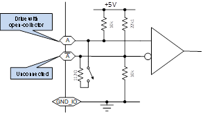
Connecting a single-ended, open-collector device to a DIO input.
The DIO#.TERM should be set to 0. The negative pin should be left disconnected / floating. Internal resistors in the drive will pull this to an appropriate level. The open-collector device should be connected between the positive pin and GND_I/O. The diagram below shows the bias resistors that are inside the drive.

Context
For more information see Digital Inputs and Outputs.
Versions
| Action | Version | Notes |
|---|---|---|
| Implemented | 02-00-00-000 |
General Information
| Type | Read/Write |
| Units | N/A |
| Range | 0 to 1 |
| Default Value | 0 |
| Data Type | Integer |
| See Also | |
|
Stored in Non Volatile Memory |
Yes |
Variants Supported
All variants are supported


