Shielding connection to the system modules

Ethernet connectors X10, X11, X18, X22, X27, X28

The shield of Ethernet cables is connected via the RJ45 connectors to the housing.

Power connectors with shield plate X12, X14, X20A, X20B, X25, X29A, X29B

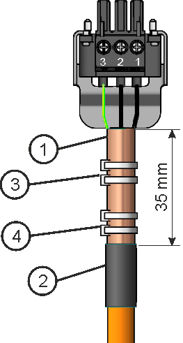
Example: Connection for the DC power by mating connector with strain relief.

  1. Strip the external cable sheath to a length of approx. 100mm, taking care not to damage the braided shield.

  2. Push the braided shield (1) back over the cable and secure with a rubber sleeve (2) or shrink sleeve.

  3. Shorten all the wires apart from the protective earth (PE) wire (green/yellow) by about 20mm so that the PE wire is now the longest wire.

  4. Strip all wires and fit wire end ferrules.

  5. Secure the braided shield of the cable to the shroud with a cable tie (3) and use a second tie (4) to fasten the cable.

  6. Wire the connector as shown in the connection diagram.

  7. Plug in the connector to the socket on the front of the MKD-C.

  8. Screw the connector in place. This ensures that there is conductive contact over a large surface area between the braided shield and the front panel.

The DC power is now connected.

Local fieldbus connectors X21A, X21B

The shield of local fieldbus cables is connected via the connector to the housing.


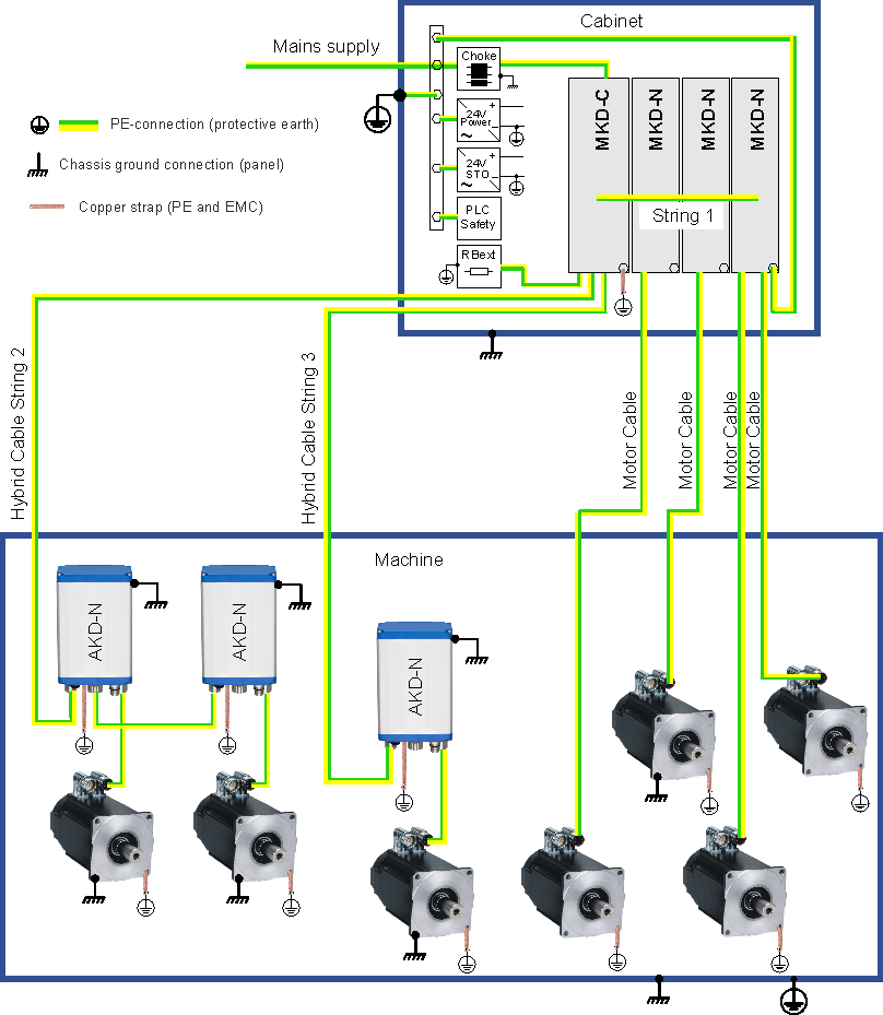
Example for system earthing