I/O Connection
Technical Data Inputs/Outputs MKD-C
|
Interface |
Electrical Data |
|---|---|
|
Digital inputs (X15B) |
|
|
Digital outputs (X15B) |
|
|
Relay output (X15A) |
|
|
STO-Enable inputs (X16A/B) |
|
|
STO-Status outputs (X15A) |
|
Technical Data Inputs/Outputs MKD-N
|
Interface |
Electrical Data |
|---|---|
|
Digital inputs (X24) |
|
|
Digital output (X24) |
|
|
STO input (X26) |
|
|
STO outputs (X24) |
|
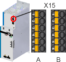
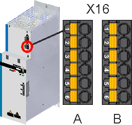
Pinout MKD-C I/O connectors X15 and X16
| X15 (I/O) | X16 (STO) |
|---|---|
|
|
Digital I/O signals are connected to X15A and X15B
|
X15A |
Signal |
Abbreviation |
Function |
Wiring Diagram |
|---|---|---|---|---|
|
1 |
Relay Output + |
Relay + |
Relay Output, programmable |
|
|
2 |
Relay Output - |
Relay - |
||
|
3 |
STO Status String 2+ |
STO-Status 2+ |
Global STO Status of String 2 |
|
|
4 |
STO Status String 2- |
STO-Status 2- |
||
|
5 |
STO Status String 3+ |
STO-Status 3+ |
Global STO Status of String 3 |
|
|
6 |
STO Status String 3- |
STO-Status 3- |
|
X15B |
Signal |
Abbreviation |
Function |
Wiring Diagram |
|---|---|---|---|---|
|
1 |
Digital Input 1 |
Digital-In 1 |
Enable, programmable |
|
|
2 |
Digital Input 2 |
Digital-In 2 |
Programmable |
|
|
3 |
Digital Input 3 |
Digital-In 3 |
Programmable |
|
|
4 |
Digital Common |
DCOM |
Common line for digital inputs |
|
|
5 |
Digital Output + |
Digital-Out+ |
Transistor Output, programmable |
|
|
6 |
Digital Output - |
Digital-Out- |
STO signals are connected to X16A and X16B
|
X16A |
Signal |
Abbreviation |
Function |
Wiring Diagram |
|---|---|---|---|---|
|
1 |
+ 24 V STO |
+ 24 V STO |
24V STO supply voltage |
|
|
2 |
STO-Enable String 2 + |
STO String 2 + |
Global STO Enable of String 2 |
|
|
3 |
||||
|
4 |
STO-Enable String 2 - |
STO String 2 - |
||
|
5 |
||||
|
6 |
STO Ground |
GND STO |
Ground of 24 V STO supply |
|
X16B |
Signal |
Abbreviation |
Function |
Wiring Diagram |
|---|---|---|---|---|
|
1 |
+ 24 V STO |
+ 24 V STO |
24V STO supply voltage |
|
|
2 |
STO-Enable String 3 + |
STO String 3 + |
Global STO Enable String of 3 |
|
|
3 |
||||
|
4 |
STO-Enable String 3 - |
STO String 3 - |
||
|
5 |
||||
|
6 |
STO Ground |
GND STO |
Ground of 24 V STO supply |
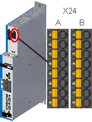
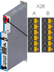
Pinout MKD-N I/O connectors X24 and X26
| X24 (I/O) | X26 (STO) |
|---|---|
|
|
Digital I/O signals are connected to X24A (axis 1) and X24B (axis 2 if available)
|
X24 |
Signal |
Abbreviation |
Function |
Wiring Diagram |
|---|---|---|---|---|
|
1 |
Digital Input 1 |
Digital-In 1 |
Enable, programmable |
|
|
2 |
Digital Input 2 |
Digital-In 2 |
Programmable |
|
|
3 |
Digital Input 3 |
Digital-In 3 |
Programmable |
|
|
4 |
Digital Common |
DCOM |
Common line for digital inputs |
|
|
5 |
Digital Output + |
Digital-Out+ |
Transistor Output, programmable |
|
|
6 |
Digital Output - |
Digital-Out- |
||
|
7 |
STO Status Out+ |
STO-Status + |
Local STO Status |
|
|
8 |
STO Status Out- |
STO-Status - |
STO signals are connected to X26A (axis 1) and X26B (axis 2 if available)
|
X26 |
Signal |
Abbreviation |
Function |
Wiring Diagram |
|---|---|---|---|---|
|
1 |
+ 24 V STO |
+ 24 V STO |
24V STO supply voltage |
|
|
2 |
STO-Enable + |
STO + |
Local STO Enable + |
|
|
3 |
||||
|
4 |
STO-Enable - |
STO - |
Local STO Enable - |
|
|
5 |
||||
|
6 |
STO Ground |
GND STO |
Ground of 24 V STO supply |