Digital Inputs and Outputs
Overview
The drive has programmable digital inputs and outputs that you can use to initiate motion, control auxiliary devices, or trigger other actions. The inputs and outputs should be wired according to the instructions in the drive Installation Manual.
Using Digital I/O
Once wired correctly, digital inputs and outputs can be used for a variety of functions such as to trigger auxiliary devices, initiate homing moves or other motion tasks, or set travel limits. This section describes the specific functionality of the programmable I/O.
I/O Tip: When using I/O devices, carefully consider the type of device you use for switches. An unsuitable switch can cause switch bounce, which in turn can cause erroneous triggers to occur. For example a low cost xx switch, as it is toggled, will bounce a few times before it turns on or off. A device monitoring these inputs frequently may interpret the bounce as multiple triggers of that I/O. The drive has the ability to reduce this type of error using some debounce techniques to ignore sudden state changes caused by bounces.
Digital Inputs
Digital inputs can be set in different modes based on the desired function. These functions are described below.
This mode is the non-use state and is the default setting for the drive. This mode is valid for all opmodes and command source combinations.
When an input configured with this mode becomes active, the drive tries to clear all active faults. This mode is edge triggered so the action occurs only once. If the condition that triggered the fault is still present, the fault condition remains. See Fault and Warning Messages for details regarding the behavior of individual faults.
This mode is valid for all opmodes and command source combinations.
This mode is used to start motion task number x, where x = the value of the associated input parameter. This input will trigger a motion task number as defined in the extra parameter field for this input.
This mode is valid for opmode 2 (position) and command source 0 (service) only.
Once started, the motion task will run until completed. Changes on the input that started the task will be ignored until the motion task is complete. If multiple inputs are configured to start a task, all of these inputs will be ignored until the task is complete. If a motion task is already active in the drive, changes on this input will be ignored.
Example:
-->DIN1.MODE 2- sets the input mode to be Start Motion Task
-->DIN1.PARAM 1- sets the Motion Task start to 1.
-->MT.LIST- confirms Motion Task 1 exists.
-->10.000 [counts] 1000.000 [rpm] 0 1001.358 [rpm/s] 1001.358 [rpm/s] 0 0 0 [ms]
<Create a rising edge of the input>
<Motion Task 1 executed>
Mode 3: Motion Task Select Bit
This mode is used to select the motion tasks stored in the drive (numbers 1 to 127) or the reference traverse/homing (0). The motion task number is presented externally at the digital inputs. The motion task set by this mode will be executed when digital input assigned to mode 4 (motion task start selected) gets a rising edge.
This mode is valid for opmode 2 (position) and command source 0 (service) only.
Example
Assume:
DIN1.MODE = DIN2.MODE=DIN3.MODE =3
The state of input 1 and 3 is 1.
The state of input 2 is 0.
Motion task 5 (5 = 20+22) will be executed.
Mode 4: Motion Task Start Selected
This mode is used to start the motion task stored in the drive by giving the motion task number. This input uses a secondary variable for the motion task number to be started with the Input trigger. The secondary variable is set by mode 3 (Motion task select bit).
Motion task number “0” initiates homing/reference traverse. A rising edge starts the motion task. A falling edge has no effect.
This mode is valid for opmode 2 (position) and command source 0 (service) only.
This mode is used to start the homing motion task on the rising edge. The falling edge has no effect on this input mode of operation.
This mode is valid for opmode 2 (position) and command source 0 (service) only.
This mode is used to start a jog move. This input mode uses a secondary variable for the jog’s velocity. The jog starts upon a rising edge. A falling edge stops the jog.
This mode is valid for opmodes 1 (velocity) and 2 (position) and command source 0 (service).
This mode is used to define the current drive position as the zero pulse for the drive EEO and sets the incremental encoder zero pulse offset. The current position, depending on the incremental encoder resolution that is set, is calculated at the rising edge (but not with a high signal at bootup of the drive) and stored as an offset. An automatic save is then generated. This function is used to perform an automatic setting of the zero pulse in one turn of the motor.
This mode is valid for all opmodes and command source combinations.
This mode is used to execute four different sets of command buffers. Each set contains two buffers: low and high, for a total of eight buffers. DINx.PARAM for this mode can be 1 to 4, and determines which set of buffers to use.
To set the high and low values of the eight buffers from the terminal screen, use the commands DIN.HCMDx and DIN.LCMDx (1<=x<=4). Use ";" to separate the two buffer commands. Each buffer contains up to 128 characters.
Example
-->DIN1.MODE 9(sets command buffer mode to digital input 1)
-->DIN1.PARAM 1(sets the first set of buffers to digital input 1)
-->DIN.LCMD1 DRV.OPMOE 0;(sets low command buffer)
Under this configuration, a rising edge in digital input 1 will set DRV.OPMODE to 1 and a falling edge will set DRV.OPMODE to 0.
You can also set the command buffers from the Digital I/O view in WorkBench; see Command Buffer
This mode is valid for all opmodes and command source combinations.
This mode is used to create an external fault.
Input state is 0 – drive regular behavior
Input state is 1 – “Fault 245 – external fault” is issued.
This mode is valid for all opmodes and command source combinations.
This mode is used to receive a physical home reference switch located on the machine to use for the different Home Types.
This mode is valid for opmode 2 (position) and command source 0 (service) only.
This mode is used to stop the motor using the deceleration variable ramp. If zero velocity is reached, the power stage is then disabled. Also see CS Parameters and Controlled Stop.
This mode is valid for all opmodes and command sources.
This mode is used to stop the motor. It is equivalent to issuing a DRV.STOP command.
This mode is valid for all opmodes and command sources 0 (service) and 2 (electronic gearing).
Mode 16: Activate Electronic Gearing
This mode starts/activates an electronic gearing procedure upon a rising edge.
This mode is valid for opmode 2 (position) and command source 2 (electronic gearing).
Mode 17: Activate Electronic Gear Position Shift
This mode is used to add a position shift to the gearing upon a rising edge. The distance of the position shift is set by the secondary variable. The secondary variable is set by DINx.PARAM. The parameter is in position units and is used to incorporate a phase shift while operating in electronic gearing mode.
This mode is valid for opmode 2 (position) and command source 2 (electronic gearing).
Example
An input is set to add a 180 degree "phase shift" when triggered. As the drive is following the electronic gearing input, the input is triggered and the motor follows the drive acceleration and deceleration rates to shift 180 degrees while maintaining the gearing synchronization.
Mode 18: Positive Limit Switch
This mode causes the input to operate as the positive limit switch. If the positive limit switch input is triggered (goes low), the positive direction motion is stopped.
This mode is valid for all opmodes and command source combinations.
-
-
When setting up the hardware limit switches, you must be certain that the switch remains in the triggered state until you move off of the switch. A very low deceleration rate combined with a high approach velocity may overshoot the switch. This action will cause the position limit warning to be canceled. The warning is not latched, therefore if the switch is overshot, additional movement in the same direction (if commanded) will be possible. This movement can cause machine damage.
Mode 19: Negative Limit Switch
This mode causes the input to operate as the negative limit switch. If the negative limit switch input is triggered (goes low), the negative direction motion is stopped.
This mode is valid for all opmodes and command source combinations.
-
-
When setting up the hardware limit switches, you must be certain that the switch remains in the triggered state until you move off of the switch. A very low deceleration rate combined with a high approach velocity may overshoot the switch. This action cancels the position limit warning. The warning is not latched, therefore if the switch is overshot, additional movement in the same direction (if commanded) will be possible. This movement can cause machine damage.
This mode is used to apply or release the brake when the drive is not active.
Input = 0: the drive controls the brake (regular drive behavior)
Input = 1: the user controls the brake (apply or release using commands)
This mode is valid for all opmodes and command source combinations.
This mode is used to limit the drive current. The current limit is set by a secondary variable; use DINx.PARAM to set the secondary variable.
This mode is valid for all opmodes and command source combinations.
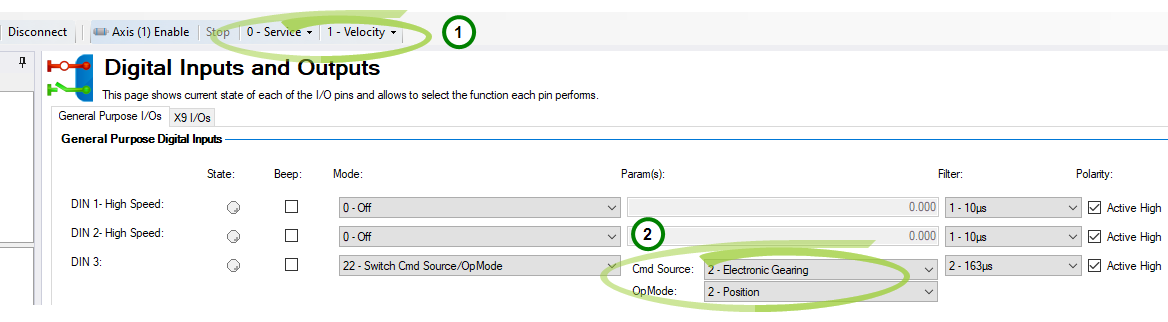
Mode 22: Switch Command Source and OpMode
This mode is used to switch between the present command source/opmode and another command source/opmode setting predetermined by the user upon the level change of a digital input. This mode is valid for all opmodes and command source combinations. Callout 1 in the screenshot below indicates the present command source/opmode that the drive is set for. This is the mode the drive is in when the digital input is not high. This low state is determined by the original settings for DRV.CMDSOURCE and DRV.OPMODE.
The drive will switch into the command source/opmode setting shown in callout 2 when the digital input level changes to high. This setting is stored by DINx.PARAM and is edited with the drop-down boxes at callout 2.
-
-
When the digital input is switched high, DRV.CMDSOURCE and DRV.OPMODE will take the values defined by DINx.PARAM. Do not perform a “drive save” in this state, or the low state and high state settings will become the same.
| DINX.PARAM | Command Source | Opmode |
|---|---|---|
|
0 |
0 - Service |
0 - Torque |
|
1 |
0 - Service |
1 - Velocity |
|
2 |
0 - Service |
2 - Position |
|
10 |
1 - Fieldbus |
0 - Torque |
|
11 |
1 - Fieldbus |
1 - Velocity |
|
12 |
1 - Fieldbus |
2 - Position |
|
N/A |
2 - Electronic Gearing |
0 - Torque |
|
N/A |
2 - Electronic Gearing |
1 - Velocity |
|
22 |
2 - Electronic Gearing |
2 - Position |
|
30 |
3 - Analog |
0 - Torque |
|
31 |
3 - Analog |
1 - Velocity |
|
32 |
3 - Analog |
2 - Position |
If more than one digital input is configured to this mode, and one of them is active, then the command source/opmode combination configured for that input will be active. If additional inputs become active, the command source/opmode combination configured for the lowest numbered will be the active one.
Example
Assume:
Input 1 is configured for electronic gearing/position.
Input 2 is configured for service/velocity.
Input 3 is configured for fieldbus/position.
The system is in service/torque.
Result:
With no inputs active, the system remains in service/torque.
If input 3 goes active first, then the system will go to fieldbus/position
If input 2 goes active first, then the system will go to service/velocity
If input 1 then goes active, then the lowest active input is now 1 so the system goes to electronic gearing/position
If input 2 then goes active, then the lowest active input is still 1 so there is no change.
If input 3 then goes inactive, then the lowest active input is still 1 so there is no change.
If input 1 then goes inactive, then the lowest active input is 2 so the system will go to service/velocity.
If input 2 then goes inactive, then there are no active inputs and the system returns to service/torque.
Mode 23: Analog In Sign Control
This mode can either change the algebraic sign of the measured analog input voltage, or zero the value using a digital input. Since the analog input voltage is used to generate command values in DRV.CMDSOURCE=3 (analog command source), Mode 23 can also be used to change the direction of movement or stop motion using a digital input in DRV.CMDSOURCE=3.
This mode is valid for all opmodes and command source 3 (analog).
The value of DINx.PARAM defines the value of a multiplication factor for the measured analog voltage. The low-byte of the DINx.PARAM value determines the value of this factor, which is multiplied by the measured analog input voltage upon a rising edge on the associated digital input. The high-byte determines the factor upon a falling edge as follows:
DINx.PARAM = 0xFFRR (F=Falling edge; R = Rising edge)
The following values are used in this mode:
| Value | Description |
|---|---|
|
0x00 |
Zero the measured analog voltage. |
|
0x01 |
Multiply the analog voltage with 1. |
|
0x02 |
Multiply the analog voltage with -1. |
|
0x03 |
Zero the measured analog voltage plus trigger in addition a software enable command. |
|
0x04 |
Multiply the analog voltage with 1 plus trigger in addition a software enable command. |
|
0x05 |
Multiply the analog voltage with -1 plus trigger in addition a software enable command. |
|
0x06 |
Zero the measured analog voltage plus trigger in addition a software disable command. |
|
0x07 |
Multiply the analog voltage with 1 plus trigger in addition a software disable command. |
|
0x08 |
Multiply the analog voltage with -1 plus trigger in addition a software disable command. |
Example 1
DINx.PARAM = 513 = 0x0201
The measured analog input voltage is multiplied with a factor of 1 upon a rising edge on the associated digital input.
The measured analog input voltage is multiplied with a factor of -1 upon a falling edge on the associated digital input.
Example 2
DINx.PARAM = 256 = 0x0100
The measured analog input voltage is multiplied with a factor of 0 upon a rising edge on the associated digital input.
The measured analog input voltage is multiplied with a factor of 1 upon a falling edge on the associated digital input.
Example 3
DINx.PARAM = 1540 = 0x0604
The measured analog input voltage is multiplied with a factor of 1 upon a rising edge on the associated digital input. Additionally, the rising edge on the associated input triggers a software enable command, similar to the DRV.EN command.
The measured analog input voltage is multiplied with a factor of 0 upon a falling edge on the associated digital input. Additionally, the falling edge on the associated input triggers a software disable command, similar to the DRV.DIS command.
Mode 25: Controlled Stop Without Enable
After performing a controlled stop the drive will not be re-enabled when the signal is high. Instead, the drive needs to be re-enabled by the user.
Suspend Motion is a feature which stops current motion, suspends further motion, but keeps the drive enabled. The axis decelerates at the rate defined by CS.DEC.
Motion is being disallowed by Suspend Motion when DRV.MOTIONDISSOURCES = 1.
Digital Outputs
Digital outputs can be set in different modes based on the desired function. These functions are outlined below.
-
-
If an output is overloaded (> 100 mA), then the output will turn off (with no indication in WorkBench) and remain off until one of the following occurs:
- The power supply driving the output is removed.
- The output is turned off from the firmware.
- The 24V supply to the AKD is power cycled.
Mode 0 – User (Default = 0):The output state is decided by the user or fieldbus. This mode is valid for all opmodes and command source combinations.
Mode 1 – Mains Ready: The output mode produces a high signal if the drive DC bus voltage is higher than the under voltage error level and lower than the over voltage error level. This mode is valid for all opmodes and command source combinations.
Mode 2 – Software Limit: This output turns on when the software limit positions are reached. This output procudes a high signal if a software limit is reached by traveling in the direction of that software limit. Software limits are set in the Limits view. In the Limits view, Position 0 is the position limit for negative travel, while Position 1 is the limit for positive travel.
This mode is valid for all opmodes and command source combinations.
Mode 3 – Move Complete: When a motion task has completed its move and the trajectory reaches zero and no following tasks are present, the move is considered complete and the output will activate when the actual position is within target_position_area, where target_position_area is as below.
target_position_area = motion_task_target_position +/- MT.TPOSWND
Mode 3 and Mode 17 (MT in Position) are almost identical. Mode 17 will trigger as soon as the load is in the position window, whereas Mode 3 will wait until the trajectory is complete before monitoring the window. Mode 17 may signal faster because of this, and can also potentially bounce out of the window temporarily.
Mode 4 – Position Error Monitor: This output mode produces a high signal when the absolute value of the position error is less than the parameter entered in the extra parameter field and the drive is enabled.
-DOUx.PARAM < PL.ERR < DOUTx.PARAM
Mode 5 – Position Greater than X: When the position is greater than the parameter entered in the extra parameter field, the output will activate.
This mode is valid for all opmodes and command source combinations.
Mode 6 – Position Less than X: When the position is less than the parameter entered in the extra parameter field, the output will activate.
This mode is valid for all opmodes and command source combinations.
Mode 7 – Warning: This output will activate when the drive experiences a warning, such as positive or negative limit switch input triggered.
This mode is valid for all opmodes and command source combinations.
Mode 8 – Enable: If you need an output to indicate that the drive is enabled, use this output mode.
This mode is valid for all opmodes and command source combinations.
Mode 10 – Motor Brake: The output mode produces a high signal if a brake is released (this is when the power is applied to the brake and the motor is free to spin). The output mode produces a low if a brake is applied (this is when power is removed from the brake and the brake is set).
This mode is valid for all opmodes and command source combinations.
Mode 11 – Drive Faults: The output mode produces a high signal if the drive has a fault.
This mode is valid for all opmodes and command source combinations.
Mode 12 – Absolute velocity greater than x: The output mode produces a high signal when the absolute value of the velocity is greater than a variable x. Use DOUTx.PARAM to set x.
This mode is valid for all opmodes and command source combinations.
Mode 13 – Absolute velocity less than x: The output mode produces a high signal when the absolute value of the velocity is less than a variable x.
Use DOUTx.PARAM to set x.
This mode is valid for all opmodes and command source combinations.
Mode 14 – Homing complete: The output mode produces a high signal when the homing process is completed.
This mode is valid for opmode 2 (position) and command source 0 (service) only.
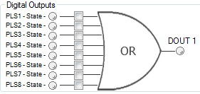
Mode 15 – Programmable Limit Switch Output: The output mode produces a high signal if at least one of the PLS.STATE bits is high (the PLS is active) and if the corresponding bit in the DOUTx.PARAM parameter also has been set to high. The DOUTx.PARAM command connects the PLS.STATE bits to the digital output itself and thus acts as an enable mask.
In mode 15 DOUTx.PARAM is set from the Digital Outputs section of the Programmable Limit Switches screen. See Programmable Limit Switch.
This mode is valid for all opmodes and command source combinations.
Example
|<- Bit 7 to 0 ->|
DOUT1.PARAM = 23 = 0b 0 0 0 1 0 1 1 1 (Binary code)
The digital output 1 is active when bit 0 or bit 1 or bit 2 or bit 4 of PLS.STATE is high. All other bits within PLS.STATE are not considered by the digital output mode due to the DOUT1.PARAM setting. Do not use decimal places for the DOUTx.PARAM parameter for this particular digital output mode.
Mode 16 – Command Buffer Active: The output mode produces a high signal when the commands in a digital input Command Buffer are being executed.
Mode 17 – Reserved
Mode 17 – MT In Position: This output turns on when the position value reaches a window around target position of the active motion task, which doesn’t have any further following motion tasks. The motion task target position window size can be assigned using MT.TPOSWND parameter.
target_position_area = motion_task_taget_position +/- MT.TPOSWND
Mode 3 and Mode 17 (MT in Position) are almost identical. Mode 17 will trigger as soon as the load is in the position window, whereas Mode 3 will wait until the trajectory is complete before monitoring the window. Mode 17 may signal faster because of this, and can also potentially bounce out of the window temporarily.
Mode 19 – Encoder Z pulse: This is the same signal as the encoder Z signal from encoder emulation (EEO, connect X9). The Z signal from Digital output mode 19 is 24V output and from X9 is RS422 output.
EEO will output the position feedback signal when it is used as an output. For detailed descriptions of EEO see Encoder Emulation .
DOUTx.STATE always returns 0 in modes 19 and 23.
Mode 20 – Controlled Stop Active: This output mode produces a high signal if no controlled stop is active. When a controlled stop is executed, the signal goes low and stays low until the controlled stop has finished.
Mode 21 – Immediate Fault Disable: This output mode produces a low signal when a fault will disable the power stage immediately, or when the hardware enable input is low. The output stays low for 500ms.
Mode 22 – In Rush Relay State: This output mode produces a low signal when the in rush relay is open. The mode produces a high signal when the in rush relay is closed.
Mode 23 – Compare Output: This output mode reflects the state of the the compare output. There are two compare engines and DOUTx.PARAM selects the engine (0 or 1) that controls this output.
Compare Engines | CMP Parameters
Mode 24 – STO Status: This output mode produces a low signal if the STO(s) are powered, and high if the STO(s) have lost power and are preventing the power stage from enabling. This is the inverse operation of the keyword STO.STATE.
Mode 25 – W&S Done: This output mode produces a high signal if wake and shake is done. This means WS.STATE is 0, in all other states the output mode produces a low signal.
Mode 26 – PWM Output: This mode outputs a configurable Pulse Width Modulation (PWM) signal. Only available on digital outputs 9, 10 and 11. See PWM Output.
Mode 27 – Warning Number: This output mode produces a high signal if a specific warning, selected by entering the warning number in DOUTx.PARAM, is active.
Summary of Opmode and Command Source Dependencies
| DINx.MODE | Mode Description | Opmode | Command Source |
|---|---|---|---|
|
0 |
Off |
All |
All |
|
1 |
Fault Reset |
All |
All |
|
2 |
Start Motion Task |
2 - Position |
0 - Service |
|
3 |
Motion Task Select Bit |
2 - Position |
0 - Service |
|
4 |
Motion Task Start Selected |
2 - Position |
0 - Service |
|
5 |
Start Home |
2 - Position |
0 - Service |
|
6 |
Start Jog |
1 - Velocity 2 - Position |
0 - Service |
|
8 |
Zero Latch |
All |
All |
|
9 |
Command Buffer |
All |
All |
|
10 |
Control Fault Relay |
All |
All |
|
11 |
Home Reference |
2 - Position |
0 - Service |
|
13 |
Controlled Stop |
All |
All |
|
15 |
Quick Stop |
All |
0 - Service |
|
16 |
Activate Electronic Gearing |
2 - Position |
2 - Electronic Gearing |
|
17 |
Electronic Gear Position Shift |
2 - Position |
2 - Electronic Gearing |
|
18 |
Positive Limit Switch |
All |
All |
|
19 |
Negative Limit Switch |
All |
All |
|
20 |
Brake Release |
All |
All |
|
21 |
Current Limitation |
All |
All |
|
22 |
Switch CmdSource/Opmode |
All |
All |
|
23 |
Analog In Sign Control |
All |
3-Analog |
| 25 | Controlled Stop without Re-enable | All | All |
| 26 | Suspend Motion | All | All |
| DOUTx.MODE | Mode Description | Opmode | Command Source |
|---|---|---|---|
|
0 |
User (Default = 0) |
All |
All |
|
1 |
Mains Ready |
All |
All |
|
2 |
Software Limit |
All |
All |
|
3 |
Move Complete |
2 - Position |
0 - Service |
|
4 |
Position Error Monitor |
2 - Position |
All |
|
5 |
Position > x |
All |
All |
|
6 |
Position < x |
All |
All |
|
7 |
Warning |
All |
All |
|
8 |
Enable |
All |
All |
|
10 |
Motor Brake |
All |
All |
|
11 |
Device Fault |
All |
All |
|
12 |
Absolute Velocity > x |
All |
All |
|
13 |
Absolute Velocity < x |
All |
All |
|
14 |
Homing Complete |
2 - Position |
0 - Service |
|
15 |
Programmable Limit Switch State |
All |
All |
| 16 | Command Buffer Active | All | All |
| 17 | MT In Position | ||
| 20 | Controlled Stop Active | All | All |
| 21 | Immediate Fault Disable | All | All |
| 22 | In-Rush Relay State | All | All |
| 23 | Compare Output | All | All |
| 24 | STO Status | All | All |
| 25 | W&S Done | All | All |
| 26 | PWM Output | All | All |
| 27 | Warning Number | All | All |