


 Electronic Gearing
Overview
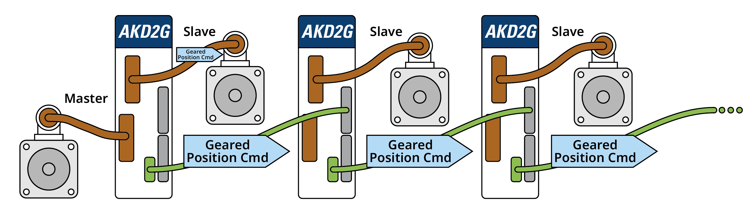
Electronic Gearing is the act of sending a command position from a master axis, to a slave axis configured to “gear” to the master and follow its position.
This feature allows one drive to be “mirrored” to multiple drives and command multiple axes from a single input signal.
Input - Gearing
The input signal can be configured from any of the drive’s feedback connectors (and any mode those connectors support, AquadB, step/direction, CW/CCW, etc).
Command Source and OpMode
To use Electronic Gearing, the command source (AXIS#.CMDSOURCE) must be set to 2 - Electronic Gearing and the opmode (AXIS#.OPMODE) must be set to 2 - Position Mode.
Electronic Gearing View
|
| Element | Property | Image | Description | Parameter | |||||
|---|---|---|---|---|---|---|---|---|---|
| 1 | Electronic Gearing Feedback Source Configuration | Feedback Source | 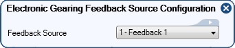
|
Select which feedback to use for the input source. | AXIS#.GEAR.FBSOURCE | ||||
| 2 | Gear Ratio In/Out Configuration | Ratio In | 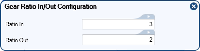
|
A ratio can be applied to the slave device. For example an In/Out ratio of 3/2 will result in two turns on the slave device for every three input. | AXIS#.GEAR.IN | ||||
| Ratio Out | AXIS#.GEAR.OUT | ||||||||
| 3 | Acceleration and Deceleration Limits Configuration | Acceleration | 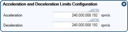
|
These values help control how quickly a slave may go into or out of electronic gearing. | AXIS#.GEAR.ACC | ||||
| Deceleration | AXIS#.GEAR.DEC | ||||||||
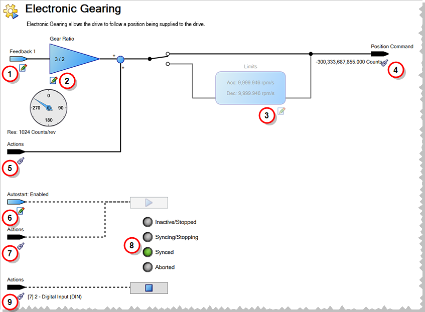
| 4 | Position Command | The Position Command displays the current position command of the axis with the gearing move applied. Clicking on this item brings you to the Position Loop view. | AXIS#.PL.CMD | ||||||
| 5 | Add Position Offset | A constant position offset may be added to the slave position using ACTION#.TASK 19 (Add Gearing Position) in the Actions Table. | |||||||
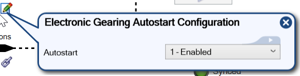
| 6 | Autostart |
|
|
Autostart initiates gearing the moment the axis is enabled.
|
AXIS#.GEAR.AUTOSTART | ||||
| 7 | Start |

|
Clicking this button will start gearing motion. Motion may also be started using ACTION#.TASK 18 (Activate Gearing) in the Actions Table. | AXIS#.GEAR.MOVE | |||||
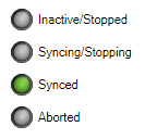
| 8 | Status |
|
A display of the slave device's status.
|
AXIS#.GEAR.STATE | |||||
| 9 | Stop |

|
Clicking this button will stop gearing motion. Motion may also be stopped using ACTION#.TASK 7 (Stop) in the Actions Table. | AXIS#.STOP |
Synchronization
When the drive is enabled and Electronic Gearing is configured, the drive attempts to achieve Electronic Gearing Synchronization. Once synchronized, the slave’s command position follows the master exactly. To prevent uncontrolled motion, acceleration and deceleration limits can be configured to limit how quickly the slave goes in and out of Electronic Gearing Synchronization.
Achieving Synchronization
When Electronic Gearing is enabled, the slave begins keeping track of all motion that has occurred on the master – even if the slave cannot keep up with the master due to AXIS#.GEAR.ACC. While the slave is trying to catch up to the master, the slave remains in an unsynchronized state with the slave’s trajectory being limited by AXIS#.GEAR.ACC.
When the slave achieves the master’s velocity scaled by the gear ratio, the slave transitions into the Synchronized state. From this point forward, AXIS#.GEAR.ACC is no longer active and the slave follows the master regardless of the trajectory.
During the phase of achieving synchronization, the slave only tracks the master up to the acceleration limit defined by AXIS#.GEAR.ACC, meaning the slave will not match the master and some position accuracy is lost.
Leaving Synchronization
If Electronic Gearing is canceled (change of opmode, cmdsource, or AXIS#.STOP is issued), the axis comes out of synchronization and is limited by the Electronic Gearing deceleration limit.
Limits
When a limit is hit (HWLS or SWLS), Electronic Gearing Synchronization is lost and a controlled stop is issued to bring the axis to rest. When the limit switch condition has been lifted, Gearing Synchronization starts again.
Electronic Gearing has additional acceleration/deceleration limits:
-
- AXIS#.GEAR.ACC is ONLY used when the slave axis is starting from rest, and AXIS#.GEAR.DEC is ONLY used when the slave is coming out of synchronization and headed to a zero velocity state.
Limiting Acceleration After Synchronization
AXIS#.GEAR.ACC and AXIS#.GEAR.DEC are only active while trying to achieve synchronization or leaving synchronization. For smoothing the profile once synchronization is achieved, use AXIS#.PL.FILTERTIME. This gives performance similar to an S-Curve profile. This is very useful if the gearing master has low resolution.


