


 Position Loop
Overview
The position loop is active when the drive operates in position mode (AXIS#.OPMODE = 2). The parameters that govern the position loop are shown in the Position Loop view. The various types of tuning inside the drive adjust these parameters, so normally the position loop parameters do not need to be adjusted in the position loop screen.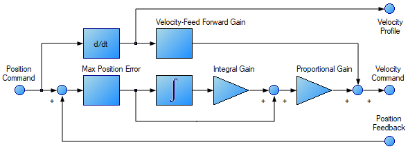
Tabs in the Position Loop View
The position loop view includes the above active block diagram. If a block within the diagram is clicked on, the appropriate tab opens below.
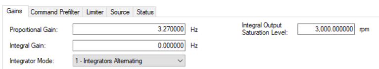
- Gains: This tab shows the gains for the position loop.
Element Description Command Proportional Gain Sets the proportional gain of the position regulator PID loop. AXIS#.PL.KP Integral Gain Sets the integral gain of the position regulator PI loop. AXIS#.PL.KI Integral Output Saturation Limits the output of the position loop integrator by setting the output saturation. AXIS#.PL.INTOUTMAX Integrator Mode Sets whether the velocity mode is:
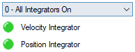
- All Integrators On - always on
- Integrators Alternating - Integrators alternate depending upon the Trajectory Velocity command.
The indicator lights show which integrator is currently in effect. When the lights are orange it indicates that it is not known which integrator is active.
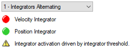
AXIS#.VL.KIMODE Integrator Threshold Sets the velocity command threshold when the position loop integrator turns off. AXIS#.PL.KITHRESH Trajectory Command AXIS#.TRAJ.VCMD Feed Forward Gain Sets the gain for the velocity feedforward (a scaled derivative of the position command is added to the velocity command value) AXIS#.VL.KVFF - Command Prefilter:
Element Description Filter Time Sets the period of a "boxcar" moving average filter on the position command. When this value is greater than zero, the filter is active. Corner Frequency Sets the frequency of a second order lowpass on the trajectory position command. When this value is greater than zero, the filter is active. Q value Sets the damping parameter of a second order lowpass on the trajectory position command. 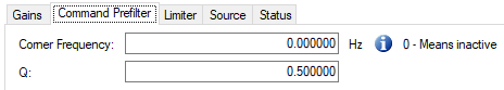
-
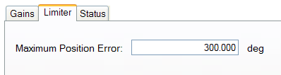
Limiter: The value in the Maximum Position Error box (AXIS#.PL.ERRFTHRESH ) limits the position error (AXIS#.PL.ERR ) that can be present. When the maximum position error is exceeded, the drive generates fault F6001 , Following Error. If the maximum position error is set to 0 (default) then the maximum position error is ignored.
-
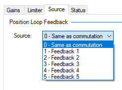
Source: This tab provides the ability to choose the desired position loop feedback (AXIS#.PL.FBSOURCE ). Please see Axis Feedback View, to configure as well as choose the desired loop feedback.
-
Status: This tab shows the present value of commanded position (AXIS#.PL.CMD), position feedback (AXIS#.PL.FB ), position error (AXIS#.PL.ERR ), and velocity command (AXIS#.VL.CMD).
Position Loop Default Behavior and Changes
By default, only a proportional gain
Position Loop Changes Based on Slider Tuning
Slider Tuning (see Slider Tuning) adjusts the proportional gain of the position loop (along with velocity loop view parameters; see Velocity Loop). If the bandwidth is adjusted using the slider tuner, then when returning to the position loop screen, there will only be a change to the proportional gain. No adjustment is made to the integral gain or feedforward gain through the slider tuner. The integral saturation levels are not applicable when the integral gain is set to 0. In the Gains tab, the boxes for these values may be populated with default values whether or not the integral gain is set to 0.
Position Loop Changes Based on PST
When the Performance Servo Tuner (PST, see Using the Performance Servo Tuner) is used, changes are made to the position loop proportional gain, integral gain, feedforward gain and other parameters not related to the Position Loop view directly. The values adjusted are dependent on the drive, motor, load, and the PST settings.
Related Parameters


