


 Velocity Loop
Overview
The velocity loop is active when the drive operates in velocity mode (AXIS#.OPMODE = 1) or position mode (
Tabs in the Velocity Loop View
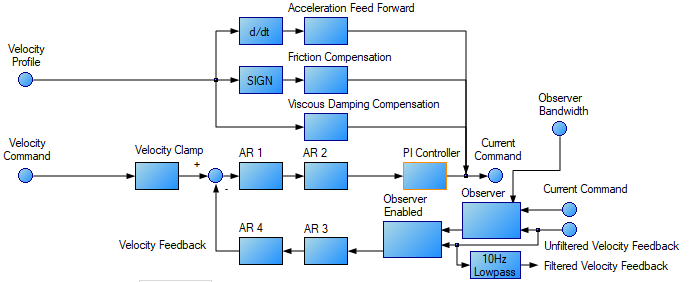
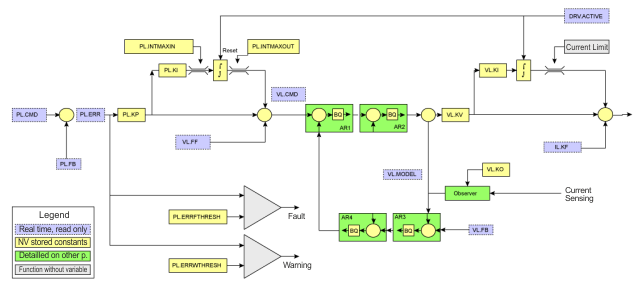
The velocity view includes the above active block diagram. If a block within the diagram is clicked on, the appropriate tab opens below.
-
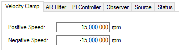
Velocity clamp: The velocity clamp affects the maximum speed of the drive when the command source is service (AXIS#.CMDSOURCE). This speed limit affects motion commanded in service motion and in motion tasks. These limits are also found in the limit screen on WorkBench. (AXIS#.VL.LIMITP and AXIS#.VL.LIMITN)
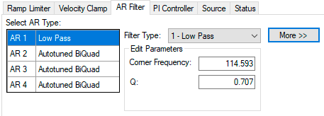
- AR Filter: AR1, AR2, AR3, and AR4 are the independent bilinear quadratic (bi-quad) filters inside the drive. AR1 and AR2 are in the forward path and AR3 and AR4 are in the feedback path. These bi-quad filters can each be configured in five different modes.
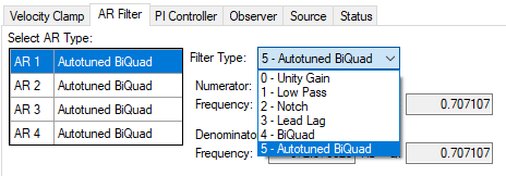
- 0–Unity Gain: The filter is off, and it will not affect the loop.
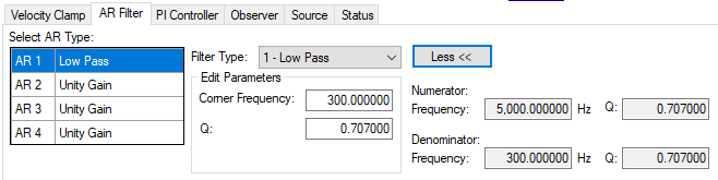
- 1–Low Pass: In modes 1, 2, and 3, the bi-quad filter is configured for each respective type of filtering. The Edit Parameters field is used to set up the filter. The actual bi-quad filter values are shown to the left:
- 2–Notch
- 3–Lead Lag
- 4–Bi-quad : A manually configured Bi-quad filter. This is an advanced tuning function.
- 5–Autotuned Biquad : When the PST sets a filter after the PST process is complete, the values are input into the Bi-Quad filter and are shown as read only values.
-
PI Controller: Set the Proportional and Integral Gain values. For more information see Tuning Guide.
The indicators show which integrator is currently in effect.
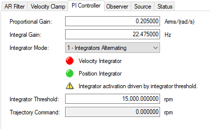
Element Description Command Proportional Gain Sets the proportional gain of the velocity loop. AXIS#.VL.KP Integral Gain Sets the integral gain of the velocity loop. AXIS#.VL.KI Integrator Mode Sets whether the velocity mode is:
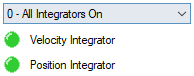
- All Integrators On - always on
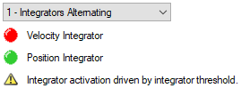
- Integrators Alternating - Integrators alternate depending upon the Trajectory Velocity command.
The indicator lights show which integrator is currently in effect. When the lights are orange it indicates that it is not known which integrator is active.
AXIS#.VL.KIMODE Integrator Threshold Sets the velocity command threshold when the position loop integrator turns off. AXIS#.PL.KITHRESH Trajectory Command AXIS#.TRAJ.VCMD - Observer: This tab contains parameters which are relevant to the status of an Observer.
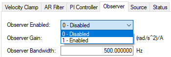
- Observer Enabled: This option turns the Observer on and off. When the Observer is in the disabled state (0), it passes the raw velocity feedback into the control loops. Associated command: AXIS#.OBS.ENABLE
- Observer Gain: This field sets the model gain of the velocity Observer. This value represents the gain of the electro-mechanical plant of the system. The system has a high gain if it responds quickly and agilely, and this number will be high. For a heavily loaded system with a large inertia mismatch, the system does not respond quickly and is sluggish. This means the value of this optin will be lower. AXIS#.OBS.KO
- Observer Bandwidth: This field sets the bandwidth of the observer in Hz. The observer passes the velocity feedback through a PID control loop that behaves like a low-pass filter with a bandwidth of this value. AXIS#.OBS.BW
- Source: Select the source for the Velocity Loop Feedback. Selections include "Same as commutation" or one of the Feedbacks.
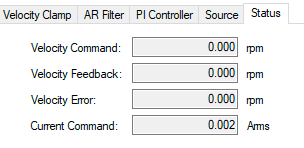
- Status: The status tab shows parameters that are relevant to the velocity loop performance.
Velocity Loop Default Settings and Changes
By default, a PI loop with a low-pass filter (AR1) is set in the drive.
The default value for the low-pass filter is 675 Hz. The low-pass filter is important for disturbance rejection, and it also reduces the audible noise of the system.
Velocity Loop Changes Based on Slider Tuning
Slider tuning (see Slider Tuning) uses the slider control to adjust the proportional gain and integral gain values of the velocity loop based on the desired bandwidth. If the bandwidth is adjusted using the slider tuner, upon returning to the velocity loop screen, different values will be present inside the proportional gain and integral gain fields. No adjustment is made to the filters automatically by using the slider tuner. Only the proportional and integral terms are adjusted.
Velocity Loop Changes Based on PST
When the PST (see Using the Performance Servo Tuner) is used, changes are made to the proportional gain, integral gain, filters, and other parameters not related to the velocity loop screen directly. The values adjusted are dependent on the drive, motor, load, and the PST settings. The filters that are adjusted by the PST are automatically put into mode 5-Autotuned Bi-quad.
No adjustments can be made to mode 5- Autotuned BiQuad filters that are set by the PST. If adjustment to the tuning of the system is desired after the PST process is completed, then these adjustments should be made in the settings of the PST. The PST process can then be repeated.
Biquad Filters
Filters in the drive all exist as digital biquad filters in the servo loops. Lowpass, LeadLag, and Resonator filters are derived by the following equations. WorkBench handles all the math involved for the user. Enter the values in the fields for the type of filter desired.
Generate a Biquad as a Lowpass at Frequency F
Numerator Frequency = 5000
Numerator Q = Sqrt(2)/2 (this is 0.707)
Denominator Frequency = F
Denominator Q = Sqrt(2)/2 (this is 0.707)
Generate a Biquad as a LeadLag at Frequency F, Gain G
Numerator Frequency = F * 10^(-G/80)
Numerator Q = Sqrt(2)/2 (this is 0.707)
Denominator Frequency = F * 10^(G/80)
Denominator Q = Sqrt(2)/2 (this is 0.707)
Generate a Biquad as a Resonator at Frequency F, Gain G, Bandwidth Q
Numerator Frequency = F
Numerator Q = 10^(-G/40) * Q
Denominator Frequency = F
Denominator Q = 10^(G/40) * Q
Block Diagram for Velocity Loop
Related Parameters
VL Parameters | AXIS#.CMDSOURCE | AXIS#.OPMODE
Related Topics


