


 Motor
Motor
Jump to a section on this page:
Overview
The Motor view is used to set up or confirm the parameters of the motor connected to the drive. In certain cases, based on the feedback type, the motor parameters are automatically set. The drive auto-detects feedback devices preset with appropriate feedback and motor parameters when AXIS#.MOTOR.AUTOSET is set to 1 (default). The values the drive uses for commutation, current, and velocity loop gains are populated automatically.
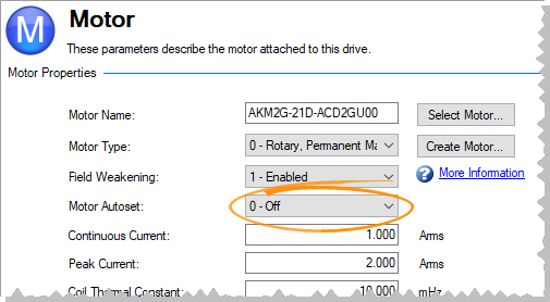
If the motor does not have a plug and play feedback device, then turn off the motor autoset feature, as shown in the screenshot below, (AXIS#.MOTOR.AUTOSET = 0) and select the appropriate motor from the motor parameter database.
All the appropriate Kollmorgen motors compatible with the AKD2G drive are contained in the motor database. For motors not listed, click Select Motor to open a custom motor view to enter the appropriate motor parameters.
See also: Motor Temperature View
Motor Setup
When motor autoset is on (AXIS#.MOTOR.AUTOSET = 1), the AKD2G automatically configures motor parameters from the data stored in a supported feedback device (see Feedback for supported devices on Kollmorgen motors). If the motor is detected automatically, the parameters in the Motor view are shaded and not accessible. If this is a non-plug and play feedback device (such as an incremental encoder or resolver), use this screen to enter motor data. Other motors can be configured from the Selecting a Motor screen.
Using the Motor View
The Motor view displays parameters related to the specific motor attached to the drive as follows:
| Element | Description | Command |
|---|---|---|
| Motor Name | The motor part number read from the autoset device or the name from the motor database. When entering a custom motor name, the motor name should not contain any spaces. | AXIS#.MOTOR.NAME |
| Motor Type | This field selects the proper electromagnetic and control parameters for a rotary motor. | AXIS#.MOTOR.TYPE |
| Field Weakening | This field allows a rotary permanent magnet motor to operate above rated speed. This field can only be set when using a rotary permanent magnet motor (AXIS#.MOTOR.TYPE = 0 or 6). See Field Weakening for information about field weakening, and Field Weakening View for information about settings. | AXIS#.MOTOR.FIELDWEAKENING |
| Motor Autoset | When set to 1, the drive automatically sets up a plug and play motor. When set to 0, access the motor database to select a catalog or custom motor. | AXIS#.MOTOR.AUTOSET |
The parameters below are specific to the electrical and mechanical characteristics of the motor connected to the AKD2G drive.
| Element | Description | Command |
|---|---|---|
| Continuous Current | Continuous current rating in ARMS. | AXIS#.MOTOR.ICONT |
| Peak Current | Peak current rating in ARMS. | AXIS#.MOTOR.IPEAK |
| Coil Thermal Constant | Coil thermal time constant in mHz. | AXIS#.MOTOR.CTF0 |
| Inductance (quad, line-line) | Inductance for quadrature (torque producing) axis in milliHenries. | AXIS#.MOTOR.LQLL |
| Inductance (direct, line-line) | Inductance for direct (flux producing) axis in milliHenries. | AXIS#.MOTOR.LDLL |
| Inductance Saturation | Quadrature axis inductance saturation characteristic. | AXIS#.MOTOR.LISAT |
| Motor Poles | Number of motor poles. | AXIS#.MOTOR.POLES |
| Motor Phase | Phase offset in degrees used to set motor commutation as required. For most devices, this is set to 0. | AXIS#.MOTOR.PHASE |
| Inertia | Rotor inertia in Kg-cm2. | AXIS#.MOTOR.INERTIA |
| Torque Constant | Proportionality constant for generated torque as a function of current in Nm/ARMS. | AXIS#.MOTOR.KT |
| EMF Constant | Proportionality constant for voltage generated at the motor coils as a function of speed. | AXIS#.MOTOR.KE |
| Motor Resistance | Winding resistance in Ohms. | AXIS#.MOTOR.R |
| Maximum Voltage | Maximum rated voltage in VRMS. | AXIS#.MOTOR.VOLTMAX |
| Maximum Speed | Maximum rated speed. | AXIS#.MOTOR.VMAX |
| Phase Adv. Gain (1st order) | Motor 1st polynomial coefficient for phase advance | AXIS#.MOTOR.PHSADVK1 |
| Phase Adv. Gain (2nd order) | Motor 2nd polynomial coefficient for phase advance | AXIS#.MOTOR.PHSADVK2 |
Selecting a Motor
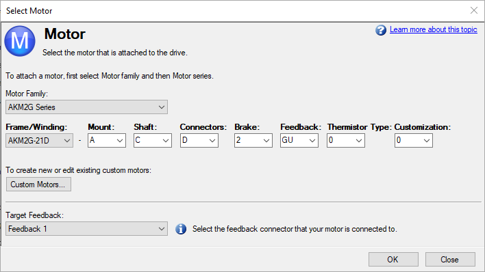
Select Motor opens a screen to configure a non-plug and play motor or custom motor.
When this screen opens, WorkBench displays by default the motor that matches the current motor name attached to the axis. WorkBench searches for a matching motor as follows:
- WorkBench checks the motor name with custom motors for a match.
- If a match is not found, then WorkBench checks the name with the standard motors database for a match.
- If a match is not found, then an AKM motor is selected.
For non-plug and play motors, a database of catalog motors is available based on the different Kollmorgen motor families. When selecting a motor family, a part number appears according to the selected motor family. The part number can be changed, as needed, and the complete motor name appears according to the selection. This complete motor name is sent to the drive. The portions of the part number labeled in bold are required values.
The Target Feedback selects which feedback connector the motor is connected to.
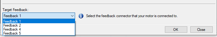
If the target feedback is changed, AXIS#.IL.FBSOURCE is changed automatically to make the commutation source match the correct feedback. AXIS#.VL.FBSOURCE and AXIS#.PL.FBSOURCE is changed to 0 to use the same source as AXIS#.IL.FBSOURCE.
-
- If the targeted feedback does not support the feedback type selected using the motor part number, the application will try to match the feedback type using an SFA adapter.
Configuring Custom Motors
From the Select Motor screen, click Custom Motor to create and edit custom motors in the following screen:
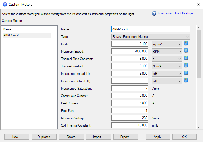
This view allows import or export of a motor parameter file or creation of a custom motor. The appropriate parameters must be chosen as listed. Several of the parameters allow selection of an alternate unit of measure. When building a custom motor file, do not use blank spaces in the name. Once one or more custom motors are configured, select a custom motor from the list and click OK, then the selected custom motor appears in the Select Motor screen.
The actions available in the custom motor screen include:
- New: Starts a new custom motor (with default values) or load a catalog motor for modification.
- Duplicate: Makes a copy of the highlighted motor in the custom motor list.
- Delete: Deletes the highlighted motor in the customer motor list.
- Import: Imports a motor file (*.motor) from another location
- Export: Saves the highlighted motor file (*.motor) to another location
- Apply: Accepts the entered values for the specific motor files entered.
- OK: Returns to the Motor Selection screen.
When entering any motor data, be certain the units are correct. The AKD2G drive uses the motor parameters to set up the various feedback loops and limits associated with the motor selected.
-
- If a custom motor is selected from the list, click Ok and the selected custom motor appears in the Select Motor screen.
See Non-Plug and Play Feedback Devices.
Validating Motor Parameters
Click OK in the Select Motor screen and WorkBench validates the range with the drive. An error screen appears if an error is found. Click Continue to set the motor parameters in the drive. Click Cancel to close this screen.
If errors occur while setting the motor parameters, an error screen indicates which parameters require additional attention.
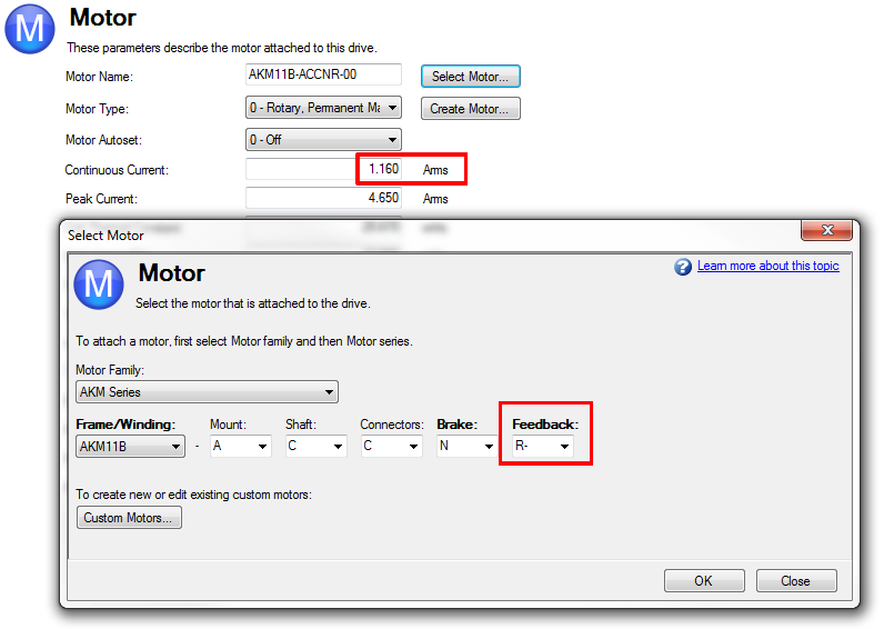
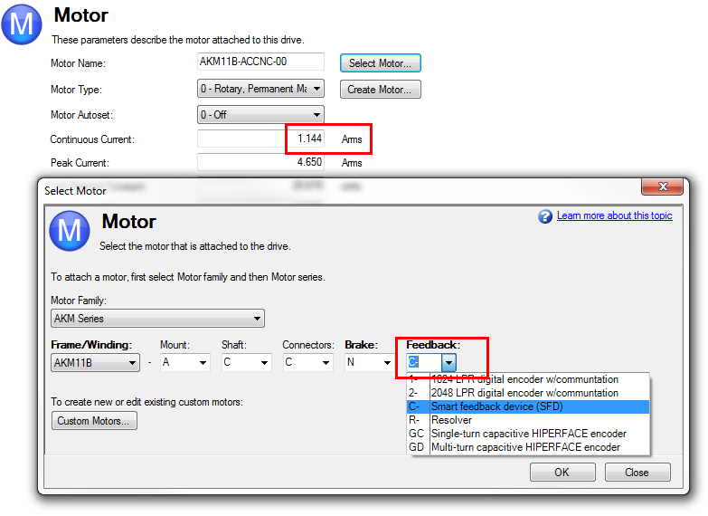
Motor Derating
Motor derating occurs while using a motor in the AKM or VLM series. If a brake is selected or a feedback type other than Resolver is selected, the continuous current is derated.
Resolver with no brake (no derate):
SFD with no brake (derated):
Related Parameters


