![]()
 Function
![]() A function calculates a result according to the current value of its inputs.
A function has no internal data and is not linked to declared instances. - Creates a PLCopen
A function calculates a result according to the current value of its inputs.
A function has no internal data and is not linked to declared instances. - Creates a PLCopen![]() A vendor -and product- independent worldwide association active in Industrial Control and aiming at standardizing PLC file formats based on XML. Axis.
A vendor -and product- independent worldwide association active in Industrial Control and aiming at standardizing PLC file formats based on XML. Axis.
Inputs
|
Input |
Data Type |
Range |
Unit |
Default |
Description |
||||||||||||
|---|---|---|---|---|---|---|---|---|---|---|---|---|---|---|---|---|---|
|
En |
BOOL |
0, 1 |
N/A |
No default |
Requests to create a PLCopen axis. |
||||||||||||
|
AxisName |
STRING |
No range |
N/A |
No default |
Axis name. |
||||||||||||
|
BusInterface |
STRING |
No range |
N/A |
No default |
Bus interface identifier:
|
||||||||||||
|
BusAddress |
DINT |
Bus dependent |
N/A |
No default |
|||||||||||||
|
AxisNumber |
UINT |
1, 256 |
N/A |
No default |
Axis number. |
||||||||||||
|
AxisType |
USINT |
0, 1 |
N/A |
No default |
|
||||||||||||
|
DriveAxisNumber |
UINT |
1, 256 |
N/A |
No default |
This one-based number specifies the axis on the drive. For a single-axis drive this number should be 1. |
||||||||||||
|
UserUnits |
DINT |
1, 2147483647 |
User units |
No default |
User unit portion of the user unit/feedback unit ratio. |
||||||||||||
|
FeedbackUnits |
DINT |
1, 2147483647 |
Feedback units |
No default |
Feedback unit portion of the user unit/feedback unit ratio. |
||||||||||||
|
Rollover |
LREAL |
0, 4294967296 |
User units |
No default |
Rollover position. 0 (zero) = no rollover. |
||||||||||||
|
UpdateRate |
UINT |
3, 9 |
N/A |
No default |
Servo update rate.
|
Outputs
|
Output |
Data Type |
Range |
Unit |
Description |
|---|---|---|---|---|
|
OK |
BOOL |
No range |
N/A |
Indicates the axis has been created. |
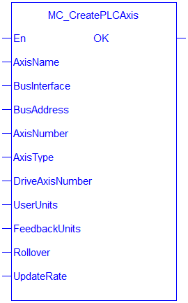
Figure 1: MC_CreatePLCAxis
Remarks
- See Function Blocks - General Rules about how inputs and outputs work.
- A call to this function is automatically generated when the application is compiled, based on the data entered in the PLCopen Axis Data dialog.
- MC_CreateAxis must be called between MLMotionInit and MLMotionStart.
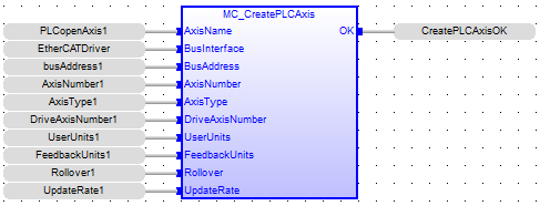
FBD Language Example
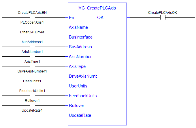
FFLD Language Example
IL Language Example
Not available.
ST Language Example
(* MC_CreatePLCAxis STStructured text - A high-level language that is block structured and syntactically resembles Pascal. Example *)
AxisName1 := 'PLCOpenAxis1';
BusName1 := 'EtherCATDriver';
BusAddress1 := 1001;
AxisNumber1 := 1;
AxisType1 := MC_AXIS_TYPE_SERVO_STEPPER;
DriveAxisNumber1 := 1;
UserUnits1 := 360;
FeedbackUnits1 := 1048576;
Rollover1 := 0;
UpdateRate1 := 3;
MC_CreateAxis(AxisName1, BusName1, BusAddress1, AxisNumber1, AxisType1, DriveAxisNumber1, UserUnits1, FeedbackUnits1, Rollover1, UpdateRate1);


