MLGearInit
![]()
 Function
![]() A function calculates a result according to the current value of its inputs.
A function has no internal data and is not linked to declared instances. - Initializes a Gear Pipe Block with user-defined settings and for use in a PLC
A function calculates a result according to the current value of its inputs.
A function has no internal data and is not linked to declared instances. - Initializes a Gear Pipe Block with user-defined settings and for use in a PLC![]() Programmable Logic Controller - A digital computer used for automation of industrial processes, such as control of machinery on factory assembly lines.
Used to synchronize the flow of inputs from (physical) sensors and events with the flow of outputs to actuators and events. program
Programmable Logic Controller - A digital computer used for automation of industrial processes, such as control of machinery on factory assembly lines.
Used to synchronize the flow of inputs from (physical) sensors and events with the flow of outputs to actuators and events. program![]() The act of performing a sequence of instructions or commands..
The act of performing a sequence of instructions or commands..
Inputs
|
Input |
Data Type |
Range |
Unit |
Default |
Description |
|---|---|---|---|---|---|
|
BlockID |
DINT |
-2147483648 to 2147483647 |
N/A |
GEAR |
ID number of a created Pipe Block. |
|
Ratio |
LREAL |
No range |
N/A |
1.0 |
Ratio of new Gear Pipe Block.
|
|
Offset |
LREAL |
No range |
N/A |
0.0 |
Offset of new Gear Pipe Block.
|
|
UseUserRatioSlope |
BOOL |
0, 1 |
N/A |
FALSE |
FALSE to use the maximum Slope.
|
|
RatioSlope |
LREAL |
No range |
1/sec |
0.0 |
User-defined limit at which step changes in Ratio are implemented.
|
|
UseUserOffsetSlope |
BOOL |
0, 1 |
N/A |
FALSE |
FALSE to use the maximum Slope.
|
|
OffsetSlope |
LREAL |
No range |
User unit/sec |
0.0 |
User-defined limit at which step changes in Offset are implemented.
|
|
Modulo |
BOOL |
0, 1 |
N/A |
FALSE |
TRUE when the mode is modulo. Modulo mode adapts the output values according to the ModuloPosition (modulo). |
Outputs
|
Output |
Data Type |
Range |
Unit |
Description |
|---|---|---|---|---|
|
Default (.Q) |
BOOL |
|
|
Returns TRUE if the Gear Pipe Block is initialized.
|
Remarks
- This function block
 A function block groups an algorithm and a set of private data.
It has inputs and outputs. is automatically called if a Gear Block is added to the Pipe Network, with user-defined settings entered in the Pipe Blocks Properties screen.
A function block groups an algorithm and a set of private data.
It has inputs and outputs. is automatically called if a Gear Block is added to the Pipe Network, with user-defined settings entered in the Pipe Blocks Properties screen. - The Pipe Block is assigned a Name, Ratio, Offset, and Slopes for changes in Ratio and Offset values.
- Choose between Modulo or Not modulo mode.
- Slopes set the limit at which step changes in Ratio and Offset are implemented.
-
-
Set the
RatioSlope < (Ratio * EtherCAT. Ethernet ofr Control Automation Technology.
EtherCAT® is an open, high-performance Ethernet-based fieldbus system.
The development goal of EtherCAT is to apply Ethernet to automation applications which require short data update times (also called cycle times) with low communication jitter (for synchronization purposes) and low hardware costs. Update Rate)
The Gear block makes a jump (without a ramp The gradual acceleration and deceleration of a stepping motor.
This is essential if performance beyond the start/stop range is required.
The slope of the ramp is a function of screw pitch, load, drive voltage and design, and motor.) from one gear to the next when the RatioSlope is greater than the Ratio change factor multiplied by the update rate scale factor.
Modulo Value
If the Gear block's input is a modulo value and the position![]() Position means a point in space which is described by different coordinates.
Depending on the used system and transformation it can consist of a maximum of six dimensions (coordinates).This means three Cartesian coordinates in space and coordinates for the orientation.
In ACS there can be even more than six coordinates.
If the same position is described in different coordinate systems the values of the coordinates are different. delta is greater than ½, the modulo value within one sample period
Position means a point in space which is described by different coordinates.
Depending on the used system and transformation it can consist of a maximum of six dimensions (coordinates).This means three Cartesian coordinates in space and coordinates for the orientation.
In ACS there can be even more than six coordinates.
If the same position is described in different coordinate systems the values of the coordinates are different. delta is greater than ½, the modulo value within one sample period![]() Motor systems having a reciprocating or oscillating motor that operates synchronously with the periodicity of the source which supplies the electrical energy.
The period of execution of a pipe is the time spent between two successive computations of set values for the same pipe. The period of execution of a pipe is specified by the PERIOD parameter of the input pipe block. in the opposite direction
Motor systems having a reciprocating or oscillating motor that operates synchronously with the periodicity of the source which supplies the electrical energy.
The period of execution of a pipe is the time spent between two successive computations of set values for the same pipe. The period of execution of a pipe is specified by the PERIOD parameter of the input pipe block. in the opposite direction![]() The orientation components of a vector in space., the Gear block cannot detect the change in the direction of motion.
The orientation components of a vector in space., the Gear block cannot detect the change in the direction of motion.
Example
- The sample period is: 1 msec.
- The Master is configured for a 360 degree modulo.
- The Master position is changed by >180 degrees within 1 msec.
- In this case, the Gear block cannot determine whether the direction is in the same or opposite direction.
Avoid Modulo Calculation Problems
- Either deactivate and reactivate the PipeNetwork when forcing the Master position with MLMstForcePos.
- Use a MLMstAbs or MLMstRel move to force the Master’s position value.
Example
To force the Master position to 0 (zero), use this code:
PipeNetwork(MLPN_DEACTIVATE);
MLMstForcePos(PipeNetwork.MASTER, 0);
PipeNetwork(MLPN_ACTIVATE);
-
-
Gear objects are normally created in the Pipe Network using the graphical engine.
You do not have to add MLGearInit function blocks to their programs.
Parameters are entered directly in pop-up windows and the code is automatically added to the current project.
FBD Language Example
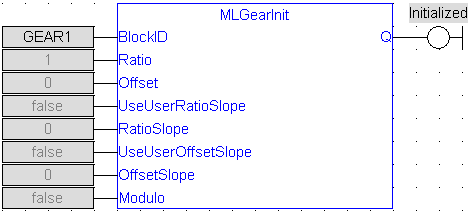
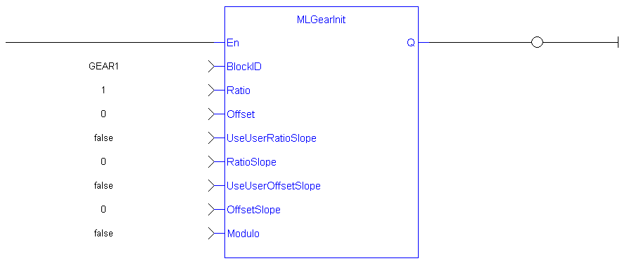
FFLD Language Example
IL Language Example
Not available.
ST Language Example
//Initialize a Gear Pipe Block named GEAR1 with:
//  Ratio = 1,Offset = 0, User Ratio Slope OFF, User Ratio
//  Slope = 0, Offset Slope = 0, and no Modulo
GEAR1 := MLBlkCreate( 'GEAR1', 'GEAR' );
MLGearInit( GEAR1, 1.0, 0.0, false, 0.0, false, 0.0, false);
See Also


