AKT2G-SDI-004-000
Jump to a section on this page:
Safety Terminal with 4 Digital Fail-safe Inputs
The AKT2G-SDI-004 is a digital input terminal with floating contacts for 24 V DC. The Bus Terminal has 4 fail-safe inputs.
With a two-channel connection, the AKT2G-SDI-004 meets the requirements of IEC 61508:2010 SIL 3, DIN EN ISO 13849-1:2015 (Cat 4, PL e), UL508, UL1998 and UL991.
The safety terminal has the typical design of an EtherCAT terminal.
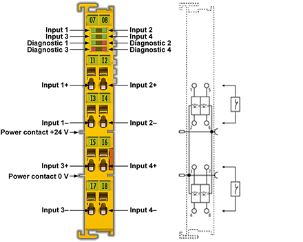
Figure 1: AKT2G-SDI-004 – safety terminal with 4 digital fail-safe inputs
-
-
Be sure to review
Related Topics: Map Input and Output to Variables
Intended Use
-
-
Caution - Risk of injury!
Safety components may only be used for the purposes described below!
The safety terminals expand the application range of the E-Bus terminal system with functions that enable them to be used for machine safety applications. The safety terminals are designed for machine safety functions and directly associated industrial automation tasks. They are therefore only approved for applications with a defined fail-safe state. This safe state is the wattless state. Fail-safety according to the relevant standards is required.
The safety terminals enable connection of:
- 24 VDC sensors (AKT2G-SDI-004) such as emergency off pushbutton switches, pull cord switches, position switches, two-hand switches, safety mats, light curtains, light barriers, laser scanner, etc.
- 24 VDC actuators (AKT2G-SDO-004 ) such as contactors, protection door switches with tumbler, signal lamps, servo drives, etc.
-
-
Test pulses
When selecting actuators, verify the AKT2G-SDO-004 test pulses do not lead to actuator switching or diagnostic message from the AKT2G-SDO-004.
The following safety components have been developed for these tasks:
- The AKT2G-SDI-004 is an EtherCAT Terminal with 4 digital fail-safe inputs.
- The AKT2G-SDO-004 is an EtherCAT Terminal with 4 digital fail-safe outputs.
These safety components are suitable for operation on the
- Kollmorgen AKT2G-ECT-000-000 series Bus Couplers
-
-
Power supply from SELV/PELV power supply unit!
The safety components must be supplied with 24 VDC by an SELV/PELV power supply unit with an output voltage limit Umax of 36 VDC. Failure to observe this can result in a loss of safety.
-
-
Follow the machinery directive!
The safety components may only be used in machines as defined in the machinery directive.
-
-
Ensure traceability!
The buyer has to ensure the traceability of the device via the serial number.
Technical Data
|
Product designation |
AKT2G-SDI-004 |
|---|---|
|
Number of inputs |
4 |
|
Status display |
4 (one green LED per input) |
|
Reaction time (read input/write to E-bus) |
typically: 4 ms, maximum: see error reaction time |
|
Error reaction time |
≤ watchdog time |
|
Cable length between sensor and terminal |
unshielded max. 100 m (0.75 or 1 mm²) shielded max. 100 m (0.75 or 1 mm²) |
|
Output current of the clock outputs |
typically 10 mA, max. 15 mA |
|
Input process image |
6 bytes |
|
Output process image |
6 bytes |
|
AKT2G-SDI-004 supply voltage (PELV) |
24 VDC (–15% / +20%) |
|
Signal voltage "0" inputs |
-3 V to 5 V (EN 61131-2, type 3) see section Characteristic curve of the inputs |
|
Signal voltage "1" inputs |
11 V to 30 V (EN 61131-2, type 3) see section Characteristic curve of the inputs. |
|
Current consumption of the modular electronics at 24 V (without current consumption of sensors) |
4 channels occupied: typically 12 mA 0 channels occupied: typically 1.4 mA |
|
Current consumption via E-bus |
4 channels occupied: approx. 200 mA |
|
Power dissipation of the terminal |
typically 1 W |
|
Electrical isolation (between the channels) |
no |
|
Electrical isolation (between the channels and the E-bus) |
yes |
|
Insulation voltage (between the channels and the E-bus, under common operating conditions) |
insulation tested with 500 VDC |
|
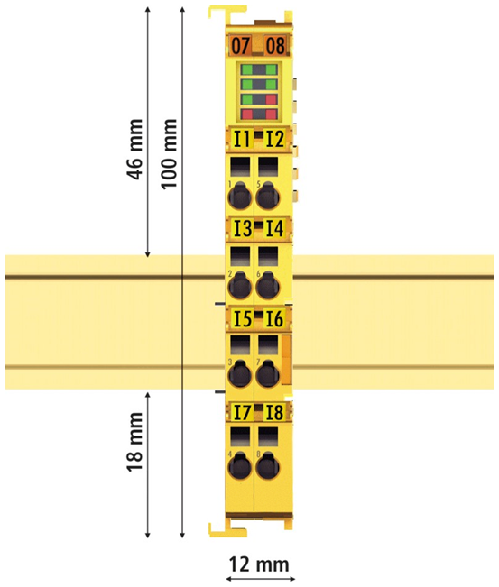
Dimensions (W x H x D) |
12mm x 100mm x 68mm |
|
Weight |
approx. 50 g |
|
Permissible ambient temperature (operation) up to SW 05 |
0 °C to +55 °C (see note in Installation Position and Minimum Distances) |
|
Permissible ambient temperature (operation) from SW 06 (week 02/2014) |
-25°C to +55 °C (see note in Installation Position and Minimum Distances) |
|
Permissible ambient temperature (transport/storage) |
-40°C to +70°C |
|
Permissible air humidity |
5% to 95%, non-condensing |
|
Permissible air pressure (operation/storage/transport) |
750 hPa to 1100 hPa (this corresponds to a height of approx. -690 m to 2450 m over sea level assuming an international standard atmosphere) |
|
Climate category according to EN 60721-3-3 |
3K3 (the deviation from 3K3 is possible only with optimal environmental conditions and also applies only to the technical data which are specified differently in this documentation) |
|
Permissible level of contamination according to EN 60664-1 |
level of contamination 2 (comply with the section Safety I/O Maintenance |
|
Impermissible operating conditions |
Safety terminals must not be used under the following operating conditions: • under the influence of ionizing radiation (that exceeds the level of the natural environmental radiation) • in corrosive environments • in an environment that leads to unacceptable soiling of the Bus Terminal |
|
EMC immunity/emission |
conforms to EN 61000-6-2 / EN 61000-6-4 |
|
Vibration/shock resistance |
conforms to EN 60068-2-6 / EN 60068-2-27 |
|
Shocks |
15 g with pulse duration 11 ms in all three axes |
|
Protection class |
IP20 |
|
Permitted operating environment |
In the control cabinet or terminal box, with minimum protection class IP54 according to IEC 60529 |
|
Permissible installation position |
see section Installation Position and Minimum Distances |
|
Approvals |
CE, cULus |
Safety Parameters
|
Key Figures |
AKT2G-SDI-004 |
|---|---|
|
Lifetime [a] |
20 |
|
Prooftest Interval [a] |
not required 1 |
|
PFHD |
1.11E-09 |
|
%SIL3 |
1.11% |
|
PFD |
8.29E-05 |
|
%SIL3 |
8.29 % |
|
MTTFd |
high |
|
DC |
high |
|
Performance level |
PL e |
|
Category |
4 |
|
HFT |
1 |
|
Element classification 2 |
Type B |
- Special proof tests are not required during the entire service life of the AKT2G-SDI-004 EtherCAT terminal.
- Classification according to IEC 61508-2:2010 (section 7.4.4.1.2 and 7.4.4.1.3)
The AKT2G-SDI-004 EtherCAT Terminal can be used for safety-related applications within the meaning of IEC 61508:2010 up to SIL3 and EN ISO 13849-1 up to PL e (Cat4).
For the calculation or estimation of the MTTFd value from the PFHD value, further information can be found in ISO 13849-1:2015 Table K.1.
Characteristic curve of the inputs
The characteristic curve of the inputs is similar to type 3 according to EN 61131-2.
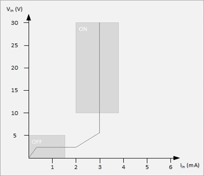
Figure 2: Characteristic curve of the inputs
Dimensions
|
|
Figure 3: Dimensions of the AKT2G-SDI-004.
Block Diagram of the AKT2G-SDI-004
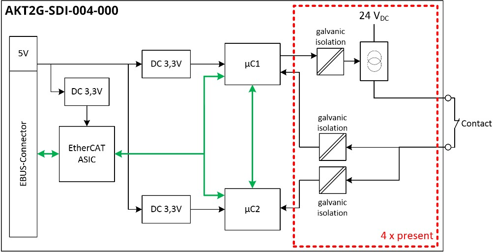
Figure 4: Block diagram of the AKT2G-SDI-004
The block diagram shows the basic configuration of a channel in the AKT2G-SDI-004. The part with a red border is present four times in the terminal.
AKT2G-SDI-004 Pin Assignment
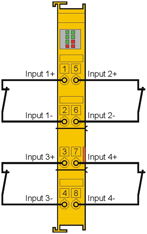
Figure 5: AKT2G-SDI-004 pin assignment
| Terminal point | Input | Signal |
|---|---|---|
|
1 |
1 |
Input 1+ |
|
2 |
Input 1- |
|
|
3 |
3 |
Input 3+ |
|
4 |
Input 3- |
|
|
5 |
2 |
Input 2+ |
|
6 |
Input 2- |
|
|
7 |
4 |
Input 4+ |
|
8 |
Input 4- |
-
-
Configurable inputs
The inputs 1 to 4 can be occupied as you want with normally closed contacts or normally open contacts. The corresponding analysis is carried out in the safety PLC.
Signal Cables
Permitted Cable Length
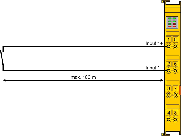
Figure 6: Permitted cable length
When connecting a single switching contact via its own continuous cabling (or via a non-metallic sheathed cable), the maximum permitted cable length is 100 m.
The use of contact points, connectors or additional switching contacts in the cabling reduces the maximum propagation.
Cable Routing
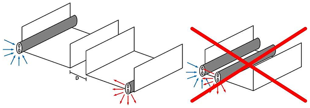
Figure 7: Cable Routing
-
-
Route the signal cable separately!
The signal cable must be routed separately from potential sources of interference (e.g., motor supply cables, 230 VAC power cables etc.)!
Interference caused by cables routed in parallel can influence the signal form of the test pulses and thus cause diagnostic messages (e.g., sensor errors or OpenLoad errors).
- D: Distance between the cable ducts should be as large as possible.
- Blue arrows: signal line.
- Red arrows: potential source of interference.
The common routing of signals, together with other clocked signals in a common cable, also reduces the maximum propagation, since crosstalk of the signals can occur over long cable lengths and cause diagnostic messages.
The test pulses can be switched off (sensor test parameter) if the connection of a common cable is unavoidable. However, this leads to a reduction in the degree of diagnostic cover when calculating the performance level.
Test Pulses
The typical length of a test pulse (switching from 24 V to 0 V and back to 24 V) is 350 µs and takes place approx. 250 times per second.
The test pulses at the outputs Input 1+ to Input 4+ are generated separately for each channel in order to be able to detect cross-circuits between the individual channels of a terminal and also between channels of different terminals. In order to generate test pulses as shown in the diagram, the sensor test active safety parameter must be set to true for the respective channels. The test cycle for all four channels is typically 4 ms. The times between the test pulses of different channels vary, thus allowing better diagnostic detection.
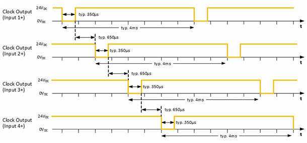
Figure 8: Typical course of test pulses of the inputs
If self-testing sensors are to be used on the safe inputs, please refer to chapter Configuration for light barriers, light grids, light curtains etc.