EtherCAT Master Settings
This tab includes configurations for the EtherCAT![]() EtherCAT is an open, high-performance Ethernet-based fieldbus system. The development goal of EtherCAT was to apply Ethernet to automation applications which require short data update times (also called cycle times) with low communication jitter (for synchronization purposes) and low hardware costs bus master.
EtherCAT is an open, high-performance Ethernet-based fieldbus system. The development goal of EtherCAT was to apply Ethernet to automation applications which require short data update times (also called cycle times) with low communication jitter (for synchronization purposes) and low hardware costs bus master.
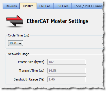
Figure 4-107: EtherCAT Master Settings
| Item | Description |
| Cycle Time | Duration of one cycle in microseconds (time = 250, 500, 1000 µs) to define the time base period for scheduling the motion and the PLC |
| Frame Size | It is the total size (in bytes) of the EtherCAT frame which is sent cyclically. The size is proportional to the number of EtherCAT slaves (and consequently the PDO data) on the network. The EtherCAT frame size may be between 84 to 1500 bytes. |
| Transmit Time | It is the time (in microseconds) that it takes to send a frame |
| Bandwidth Usage | It is an estimation of the percentage of the cycle time used to transmit a frame of data. Bandwidth |
| Working Counter Error Limit |
A configurable threshold for generating an E30 error and shutdown of EtherCAT communication. The default setting is 3 Errors in 1000 Frames. Other options are: Trigger on 1st Error, 2 Errors in 1000 Frames, 10 Errors in 1000 Frames, 100 Errors in 1000 Frames, or Disabled. If the Disabled option is selected the Master will keep the EtherCAT network running in op mode. It is up to the application to decide if it is appropriate to shut down the Master’s EtherCAT communication (MLMotionStop).
See EtherCAT Error Messages for additional working counter information. |
Table 4-25: EtherCAT Cycle Settings - Form Description
The three read-only fields display (unknown) when the Use imported file option is selected (see ENI File Tab tab). Otherwise, they are recalculated and refreshed each time that:
- A device is added or removed
- A device simulation state changes
- The Use imported file check box is cleared
Bandwidth calculation algorithm
The Bandwidth (BW) usage calculation takes into account the calculated frame size and the Ethernet![]() Ethernet is a large, diverse family of frame-based computer networking technologies that operate at many speeds for local area networks (LANs) speed (100 Megabits per second).
Ethernet is a large, diverse family of frame-based computer networking technologies that operate at many speeds for local area networks (LANs) speed (100 Megabits per second).
BW% = Transmission time / Cycle Time
With Transmission time (μsec) = (Frame![]() In networking dialect, a message is called a frame Size in bytes * 8) bits / 100 * 106 bps
In networking dialect, a message is called a frame Size in bytes * 8) bits / 100 * 106 bps
For example:
If Frame Size = 100 bytes
then Transmission Time = 100*8 / (100*106 ) = 8 μsec
If cycle time = 1000 μsec
then BW% = 8/1000 = 0.8 %


