Part 18: Test Enable and Disable of Axes
Use this procedure to test the Enable and Disable for the axes.
- This demonstrates control over each axis using the PLC and CIP Sync connection.
- In WorkBench, the status bar indicates all conditions are met to enable each axis:

Procedure
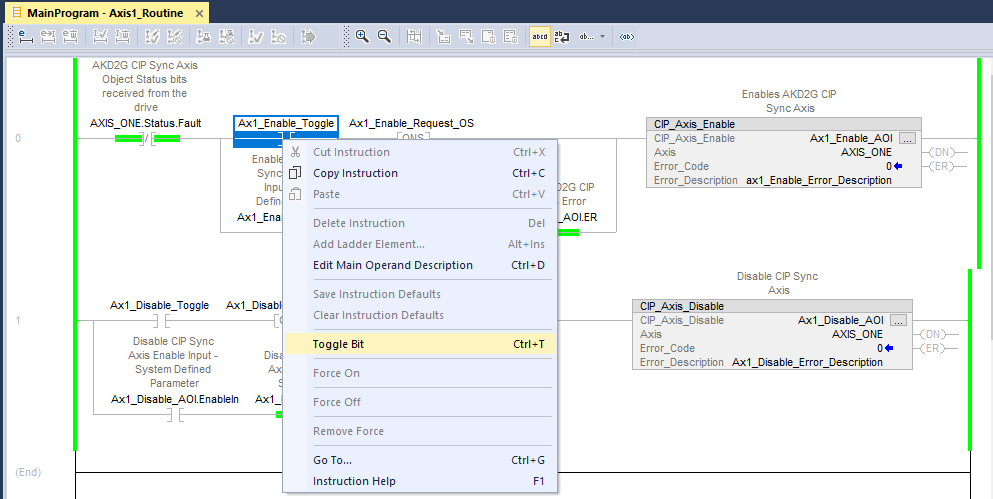
- In the Controller Organizer, navigate to MainTask > MainProgram > Axis1_Routine.
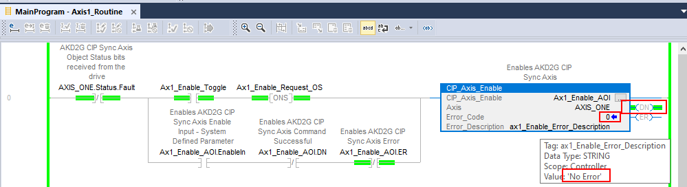
- On Rung 0, right-click on the Ax1_Enable_Toggle normally open contact.
- Select Toggle Bit.
- The output bit turns ON.
- AOI’s Error_Code = 0.
- Error_Description = No Error.
- Right-click the Ax1_Enable_Toggle normally open contact.
- Select Toggle Bit.
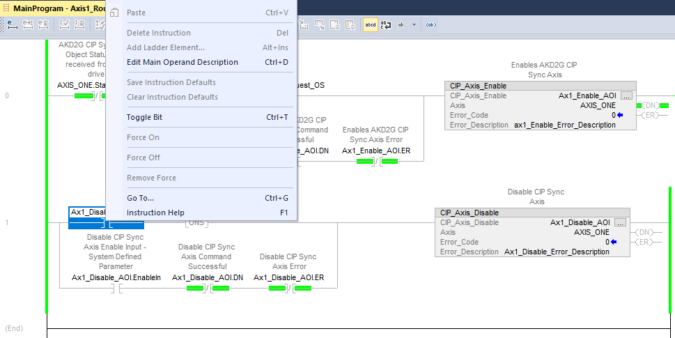
This turns the contact OFF before continuing. - On Rung 1 of the Axis1_Routine, right-click the Ax1_Disable_Toggle normally open contact.
- Select Toggle Bit.
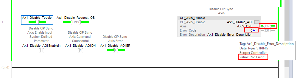
- The output bit turns ON.
- AOI’s Error_Code = 0.
- Error_Description = No Error.
- Right-click the Ax1_Disable_Toggle normally open contact.
- Select Toggle Bit.
This turns the contact OFF before continuing.
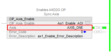
A successful CIP_Axis_Enable AOI .DN (Done) shows:
In WorkBench, the Status Bar a the bottom of the screen indicates Axis 1 is Active (and Enabled):

A successful CIP_Axis_Disable AOI .DN (Done) shows:
In WorkBench, the Status Bar at the bottom of the screen displays Axis 1 is Inactive (Disabled):

It is left up to the user to repeat this procedure for Axis2 in the Axis2_Routine.
Notes
- The Getting Started using the CIP Sync Sample Project section demonstrates other AOIs and ladder logic.
- The AOI Library, Definitions, & Functionality (CIP Sync) reference provides an Example of Usage/Programming Guidelines in each Kollmorgen supplementary AOI.
- They also demonstrate using some basic Studio 5000 motion instructions (i.e., MAS, MAJ, MAM, etc).
- A foreword on Studio 5000 instructions versus the Kollmorgen supplemental CIP Axis Add-On Instructions:
- The Kollmorgen supplemental CIP Axis Add-On Instructions use the tag name for the CIP_Axis declared in the CIP_Drive_Comms add on instruction.
- Example: In the Sample Project (or New Project) in the CIP_Drive_Comms AOI, Axis1 and Axis2 were declared as AXIS_ONE and AXIS_TWO respectively.
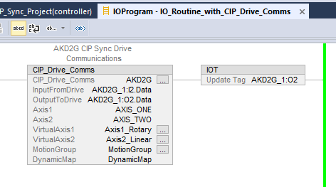
- Compare the entries for VirtualAxis1 and VirtualAxis2.
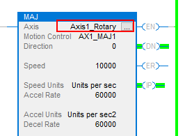
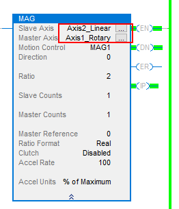
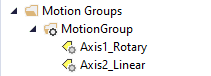
- Axis1_Rotary and Axis2_Linear respectively from the virtual axes declared in the Motion Group.
- Kollmorgen Supplementary AOIs ALWAYS use the Axis1 and Axis2 tags in the CIP_Drive_Comms for their “Axis” entry (shown above as AXIS_ONE and AXIS_TWO).
Example: - Compare to a Studio 5000 motion instruction such as the MAJ or MAG.
- In these cases the Axis is ALWAYS a virtual axis declared in the Motion Group.
- Compare to a Studio 5000 motion instruction such as the MAJ or MAG.