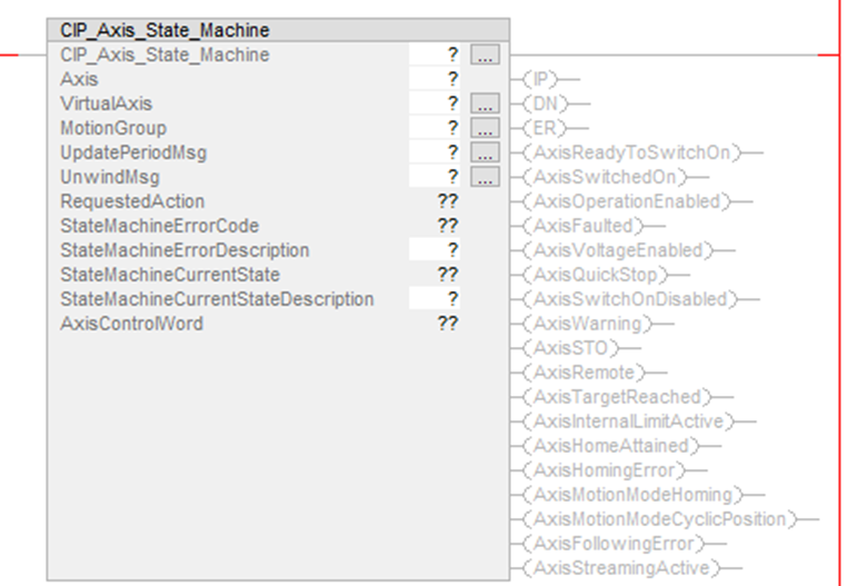
CIP_Axis_State_Machine AOI
- Each AKD2G Axis requires a corresponding CIP_Axis_State_Machine AOI to receive requested actions (commands) from the supplementary Kollmorgen CIP Axis AOIs.
- This generates operations such as Enable, Disable, Home, Fault Reset, Quick Stop, Enable Streaming, and Disable Streaming.
Use the CIP_Axis_State_Machine instruction to:
- Synchronize the AKD2G axis’ AXIS#.EIP.STREAMPERIOD with the Motion Group’s CoarseUpdatePeriod.
- Synchronize the AKD2G axis’ AXIS#.EIP.UNWIND where:
- If the Virtual Axis is rotary, AXIS#.EIP.UNWIND = Position Unwind value of the Virtual Axis.
- If the Virtual Axis is linear, the Position Unwind of the Virtual Axis is not used and the AXIS#.EIP.UNWIND is set to 2,000,000,000.
- Monitor the axis’ State Machine including:
- CIP_Axis_State_Machine AOI’s IP, DN, and ER bits
- Axis status bits
- AxisControlWord bits
- RequestedAction
- StateMachineErrorCode (if State Machine Error is present)
- StateMachineErrorDescription (if State Machine Error is present)
- StateMachineCurrentState and StateMachineCurrentStateDescription
Compatibility
The CIP_Axis_State_Machine AOI is only compatible with AKD2G-SPI drives when used with Motion Supported PLCs with Studio 5000 and the CIP Sync connection.
Required Command Source and Operation Mode
- AXIS#.CMDSOURCE = Fieldbus
- AXIS#.OPMODE = Position
The CIP_Axis_State_Machine AOI is always enabled in the Ladder routine under MainTask > MainProgram by the AOI’s EnableIn being tied to the left rail.
- The Sample project includes a CIP_Axis_State_Machine AOI for each axis in a routine under the MainTask > MainProgram called MainRoutine_with_CIP_State_Machines.
The CIP_Axis_State_Machine provides this functionality:
- Sets the Stream Period of the Axis in the AKD2G drive (on prescan) via internal MSG instructions inside the CIP_Axis_State_Machine AOI.
- Receives a Request Action from the supplemental KollmorgenAOIs to move within the CIP Sync: State Machine from one state to another to generate certain operations (i.e., fault reset).
- Monitors and displays the Status bits for the axis based on the current state.
- Displays the:
- AxisControlWord bits.
- Requested Action.
- StateMachineErrorCode and StateMachineErrorDescription (if state machine error present).
- StateMachineCurrentState and StateMachineCurrentStateDescription.
Operands
These entries are required by the user.
|
Operand |
Data Type |
Format |
Description |
|---|---|---|---|
|
CIP_Axis_State_Machine |
CIP_Axis_State_Machine |
Tag |
Tag name for this instance of the AOI. |
|
Axis |
CIP_Axis |
Tag |
User tag for AKD2G drive’s axis defined in the CIP_Drive_Comms AOI fields Axis1 or Axis2. |
|
VirtualAxis |
AXIS_VIRTUAL |
Tag |
|
|
MotionGroup |
MOTION_GROUP |
Tag |
User tag defining the name of the MotionGroup controlling the given AKD2G drive. |
|
UpdatePeriodMsg |
MESSAGE |
Tag |
User tag defining the name of the UpdatePeriod MSG internal to the CIP_Axis_State_Machine AOI. |
|
UnwindMsg |
MESSAGE |
Tag |
User tag defining the name of the Unwind MSG internal to the CIP_Axis_State_Machine AOI. |
|
StateMachineErrorDescription |
STRING |
Tag |
|
|
StateMachineCurrentStateDescription |
STRING |
Tag |
|
Structure
These fields are not entered by the user and are populated automatically with Read Only data once the Operands (in the Operand table for this AOI) are entered or presented as output data (bits).
|
Mnemonic |
Type/Usage |
Data Type |
Description |
|---|---|---|---|
|
.EnableIn |
Input |
BOOL |
The Enable Input bit indicates the instruction is enabled. |
|
.EnableOut |
Output |
BOOL |
The Enable Output bit is the output of the Enable Input (.EnableIn) bit. |
|
.IP |
Output |
BOOL |
In Process bit. |
|
.DN |
Output |
BOOL |
Done bit. |
|
.ER |
Output |
BOOL |
Error bit. |
|
RequestedAction |
Output |
INT |
|
|
StateMachineErrorCode |
Output |
INT |
|
|
StateMachineCurrentState |
Output |
INT |
|
|
AxisControlWord |
Output |
INT |
|
|
.AxisReadyToSwitchOn |
Output |
BOOL |
|
|
.AxisSwitchedOn |
Output |
BOOL |
|
|
.AxisOperationEnabled |
Output |
BOOL |
|
|
.AxisFaulted |
Output |
BOOL |
|
|
.AxisVoltageEnabled |
Output |
BOOL |
|
|
.AxisQuickStop |
Output |
BOOL |
|
|
.AxisSwitchedOnDisabled |
Output |
BOOL |
|
|
.AxisWarning |
Output |
BOOL |
|
|
.AxisSTO |
Output |
BOOL |
|
|
.AxisRemote |
Output |
BOOL |
|
|
.AxisTargetReached |
Output |
BOOL |
|
|
.AxisInternalLimitActive |
Output |
BOOL |
|
|
.AxisHomeAttained |
Output |
BOOL |
|
|
.AxisHomingError |
Output |
BOOL |
|
|
.AxisMotionModeHoming |
Output |
BOOL |
|
|
.AxisMotionModeCyclicPosition |
Output |
BOOL |
|
|
.AxisFollowingError |
Output |
BOOL |
|
|
.AxisStreamingActive |
Output |
BOOL |
State Machine Requested Actions
|
Requested Action # |
Requested Action |
Used By AOI |
State Machine AOI Internal Mode |
|---|---|---|---|
|
0 |
Idle |
CIP_Axis_Disable_Streaming |
Mode 0 |
|
1 |
Disable |
CIP_Axis_Disable |
Mode 1 |
|
2 |
Enable |
CIP_Axis_Enable |
Mode 2 |
|
3 |
Reset Faults |
CIP_Axis_Fault_Reset |
Mode 3 |
|
4 |
Quick Stop |
CIP_Axis_Quick_Stop |
Mode 4 |
|
5 |
Start Home Move |
CIP_Axis_Home |
Mode 5 |
|
6 |
Enable Cyclic Position Streaming |
CIP_Axis_Enable_Streaming |
Mode 6 |
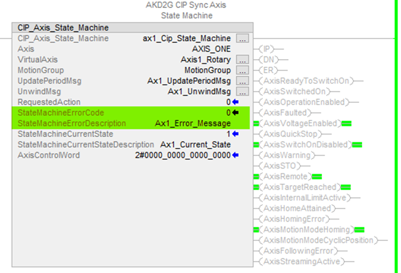
In most cases after the Requested Action is completed, the reported RequestedAction is 0 (Idle).
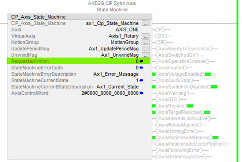
Figure 1: State Machine RequestedAction shown in the field highlighted in the AOI.
State Machine Current States and Descriptions
|
Current State # |
State Description |
|---|---|
|
0 |
Not Ready To Switch On |
|
1 |
Switch On Disabled |
|
2 |
Ready To Switch On |
|
3 |
Switched On |
|
4 |
Operation Enabled |
|
5 |
Quick Stop Active |
|
6 |
Fault Reaction Active |
|
7 |
Faulted |
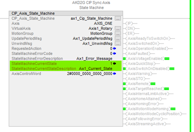
Hover the mouse cursor over the tag for StateMachineCurrentStateDescription to view the Current State Description.
Execution
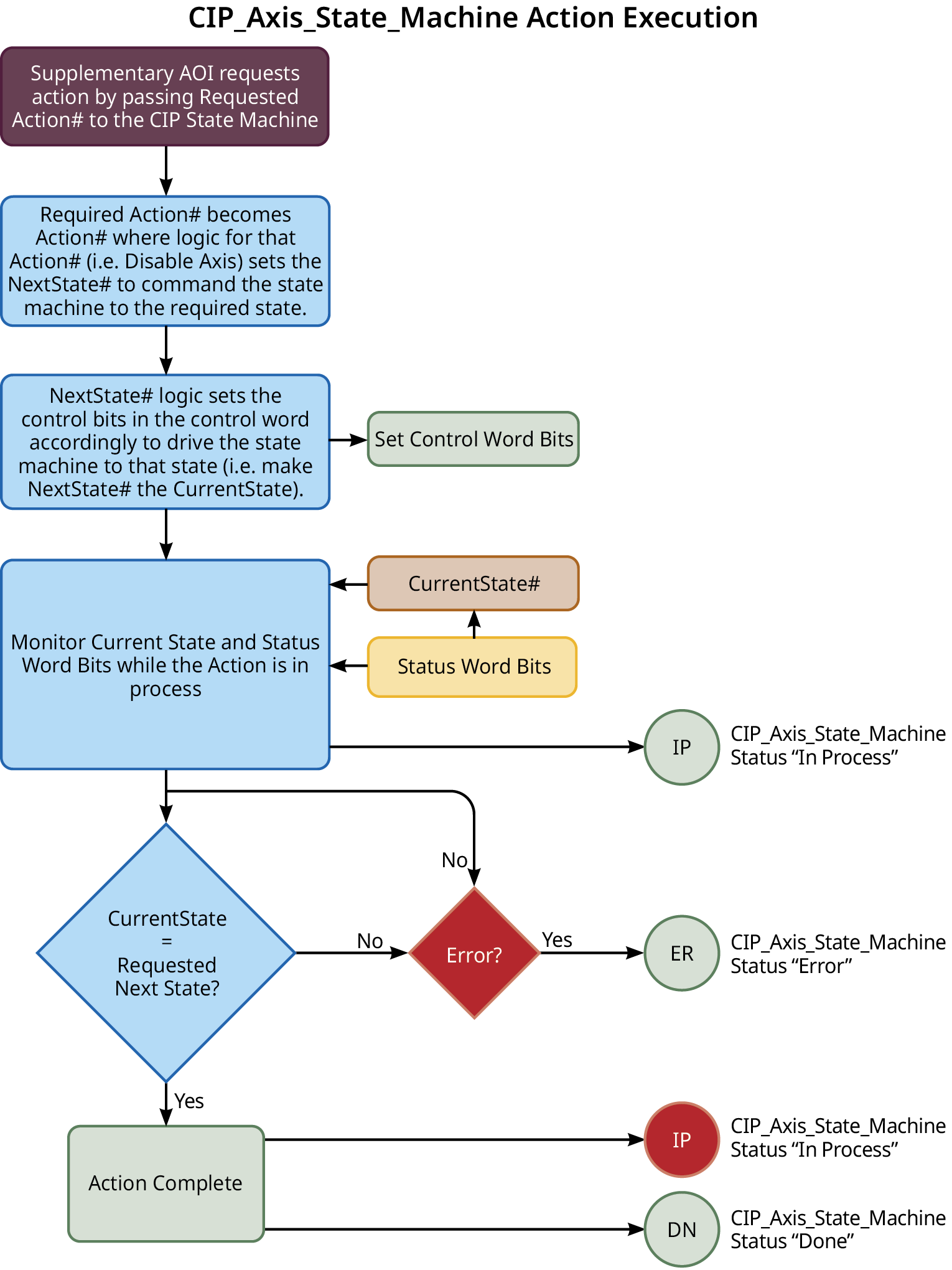
Changes to Axis Status Bits and Control Word bits Description
- All status bits are updated from the drive.
- See Status Word in CIP Sync Response Assembly Data Structure (106).
- Control Word bits descriptions and functions are described under Control Word in CIP Sync Command Assembly Data Structure (105).
- See CIP Sync: State Machine.
Example of Usage/Programming Guidelines
From the Sample project under MainTask > MainProgram, a routine named MainRoutine_with_CIP_State_Machines contains the CIP_Axis_State_Machine AOIs for each axis (only Axis1 shown below).
There are JSR (Jump To Subroutines) where each subroutine is the ladder logic for each respective axis ( i.e., Axis1_Routine, Axis2_Routine, etc.)
The CIP_Axis_State_Machine AOI(s) are tied unconditionally to the left rail and execute on every scan.
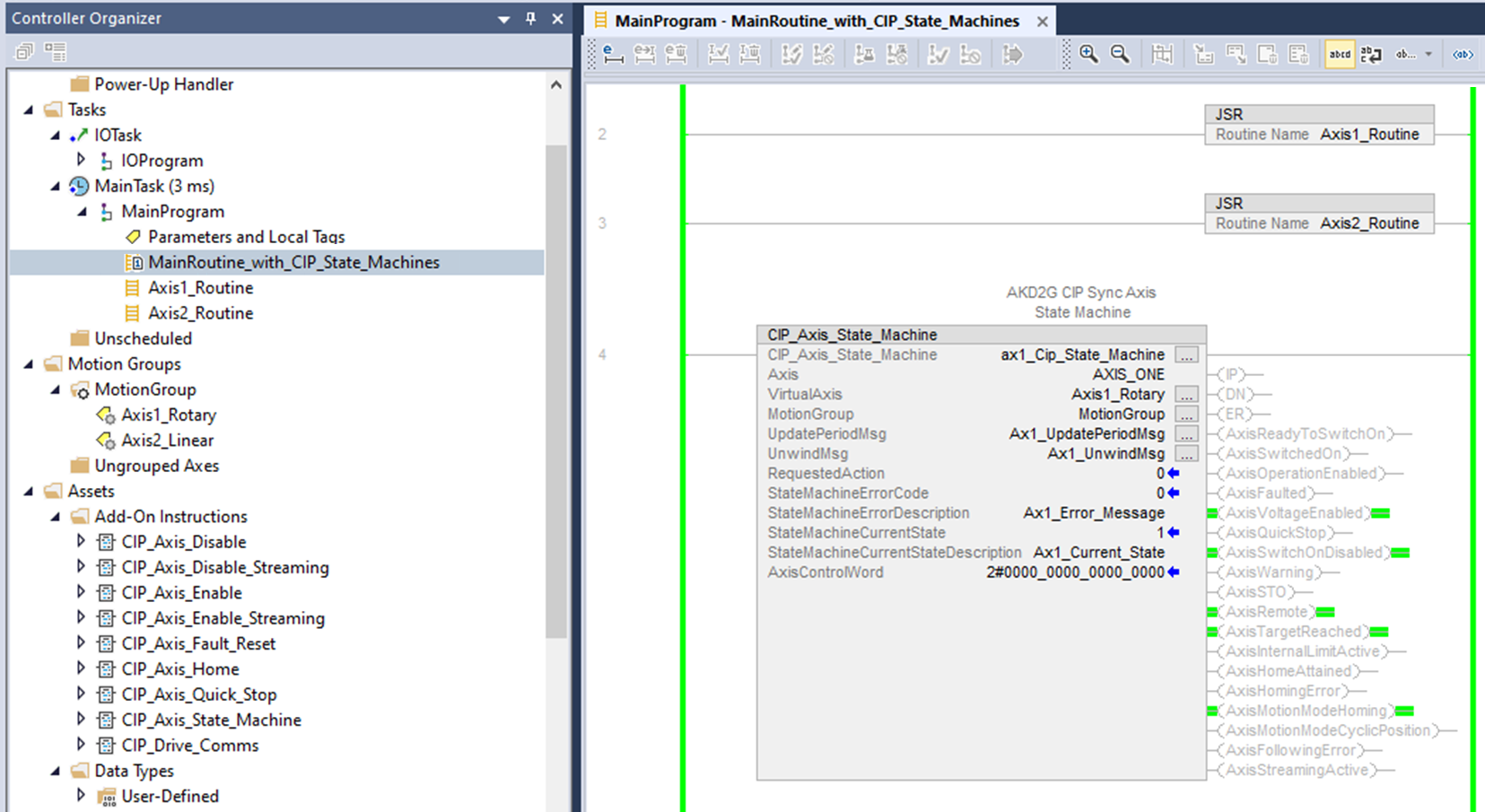
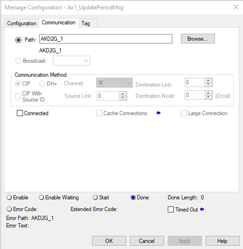
The UpdatePeriodMSG and UnwindMsg messages inside the CIP_Axis_State_Machine AOI must be configured correctly to point to the correct:
- Attribute IDs (of the parameters for the axis in the AKD2G drive).
- Module path for the CIP_Axis_State_Machine to operate without error (.ER).
Axis 1 CIP_Axis_State_Machine
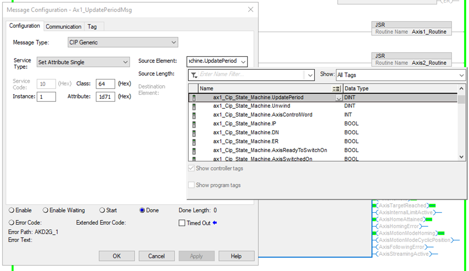
UpdatePeriodMsg
|
ID |
Instance |
Attribute |
Name |
Data Type |
Access |
User Mappable |
|---|---|---|---|---|---|---|
|
7537 |
1 |
0x1d71 |
AXIS1.EIP.STREAMPERIOD |
Signed32 |
Read/Write |
Yes |
Axis 1:
Message Configuration:
|
Message Type |
CIP Generic |
|
Service Type |
Set Attribute Single |
|
Service Code |
10 |
|
Class |
64 |
|
Instance |
1 (Axis 1) |
|
Attribute |
1d71 (hex), AXIS#.EIP.STREAMPERIOD |
|
Destination Element |
|
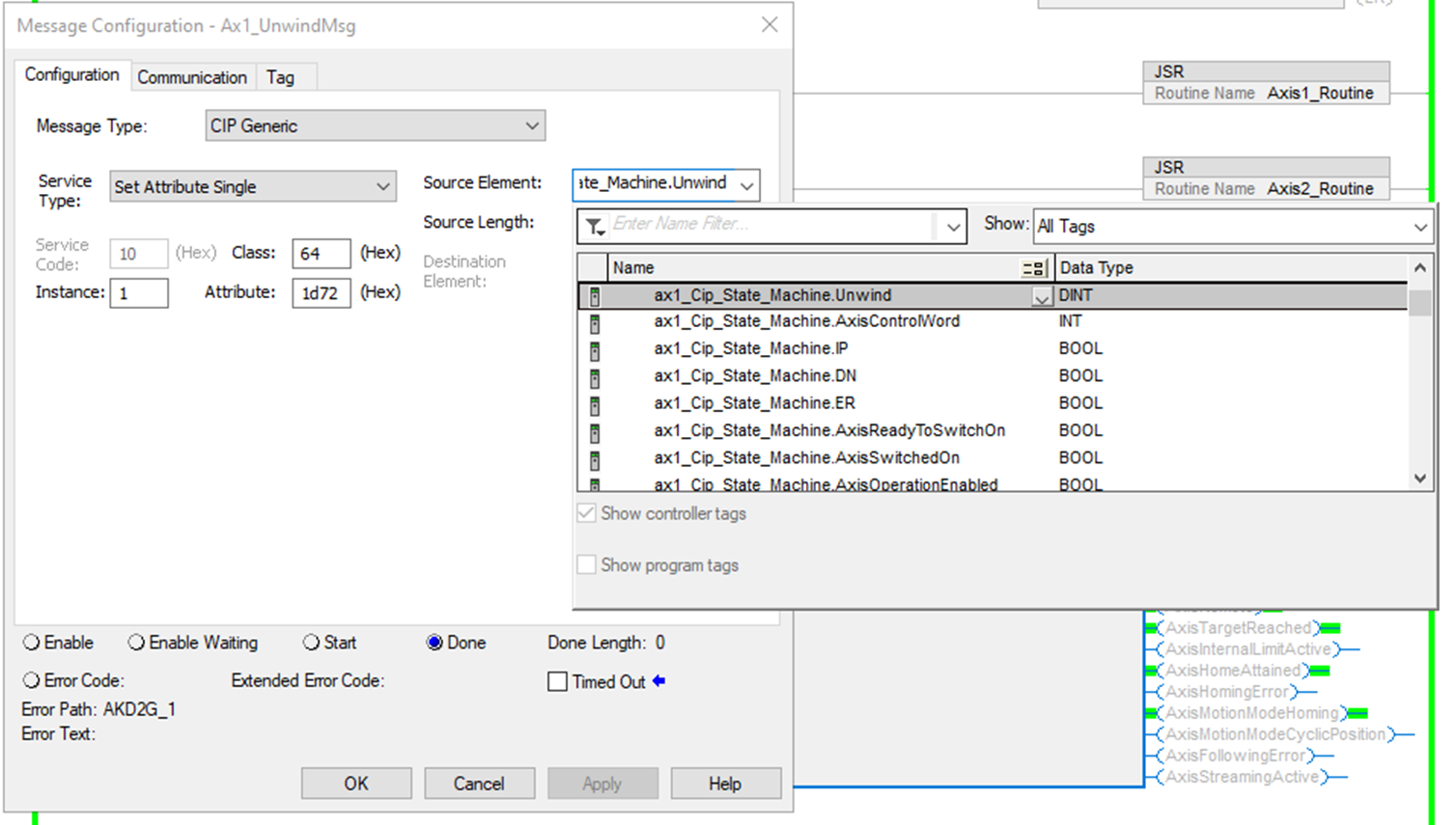
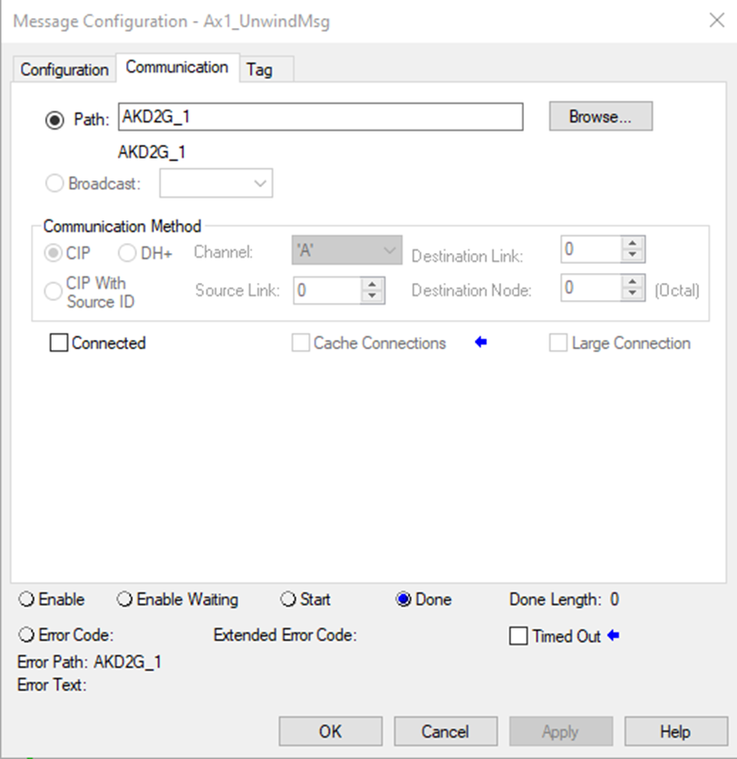
UnwindMsg
|
ID |
Instance |
Attribute |
Name |
Data Type |
Access |
User Mappable |
|---|---|---|---|---|---|---|
|
7538 |
1 |
0x1d72 |
AXIS1.EIP.UNWIND |
Signed32 |
Read/Write |
Yes |
Axis 1:
Message Configuration:
|
Message Type |
CIP Generic |
|
Service Type |
Set Attribute Single |
|
Service Code |
10 |
|
Class |
64 |
|
Instance |
1 (Axis 1) |
|
Attribute |
1d72 (hex), AXIS#.EIP.UNWIND |
|
Destination Element |
|
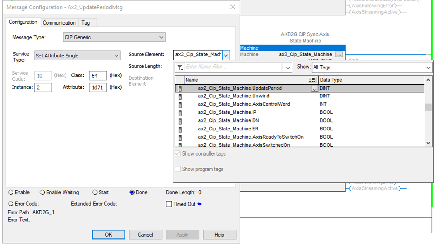
Axis 2 CIP_Axis_State_Machine
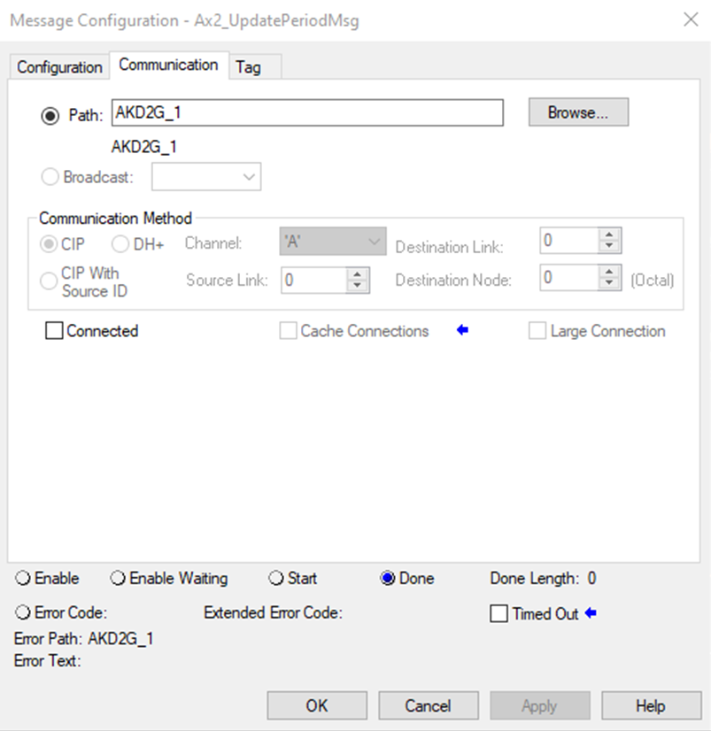
UpdatePeriodMsg
|
ID |
Instance |
Attribute |
Name |
Data Type |
Access |
User Mappable |
|---|---|---|---|---|---|---|
|
73073 |
2 |
0x1d71 |
AXIS2.EIP.STREAMPERIOD |
Signed32 |
Read/Write |
Yes |
Axis 2:
Message Configuration:
|
Message Type |
CIP Generic |
|
Service Type |
Set Attribute Single |
|
Service Code |
10 |
|
Class |
64 |
|
Instance |
2 (Axis 2) |
|
Attribute |
1d71 (hex), AXIS#.EIP.STREAMPERIOD |
|
Destination Element |
|
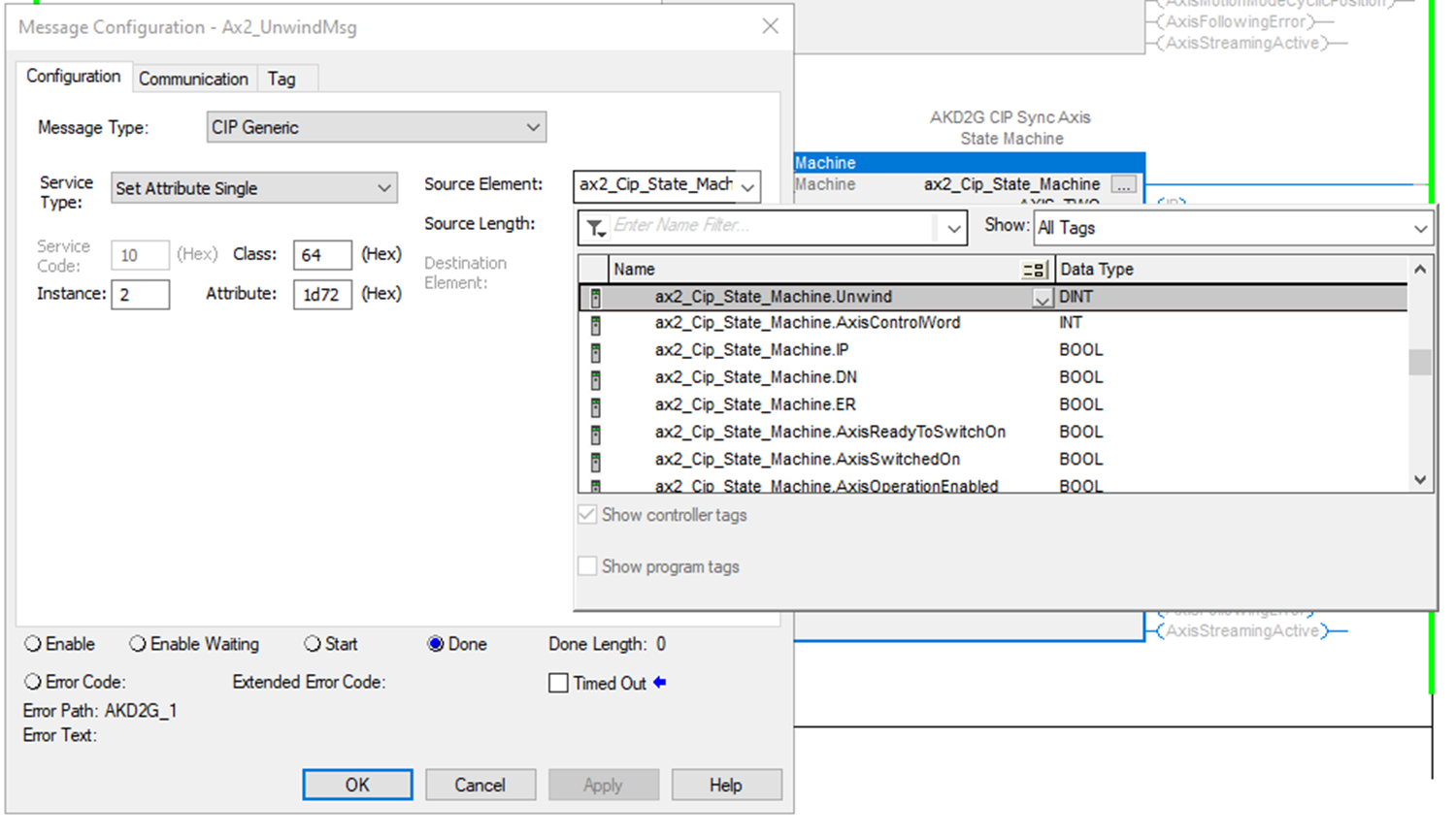
UnwindMsg:
|
ID |
Instance |
Attribute |
Name |
Data Type |
Access |
User Mappable |
|---|---|---|---|---|---|---|
|
73074 |
2 |
0x1d72 |
AXIS2.EIP.UNWIND |
Signed32 |
Read/Write |
Yes |
Axis 2:
Message Configuration:
|
Message Type |
CIP Generic |
|
Service Type |
Set Attribute Single |
|
Service Code |
10 |
|
Class |
64 |
|
Instance |
2 (Axis 2) |
|
Attribute |
1d72 (hex), AXIS#.EIP.UNWIND |
|
Destination Element |
|

Troubleshooting
- State Machine Error Codes are found in the StateMachineErrorCode and StateMachineErrorDescription fields.
- Hover the mouse cursor over the StateMachineErrorDescription tag to view the error description.
Error Code Syntax: XYY
-
X = Mode the Fault occurs in
-
YY = Error ID
State Machine Error Codes and Error Descriptions
|
Error Code |
Error Description |
Additional Description |
Mode |
|---|---|---|---|
|
0 |
No Error |
|
N/A |
|
In Fault Reaction Active state while trying to disable. |
|
1 - Disable Axis |
|
|
In Fault state while trying to disable. |
|
1 - Disable Axis |
|
|
In Fault Reaction Active state while trying to enable. |
|
2-Enable Axis |
|
|
In Fault state while trying to enable. |
|
2-Enable Axis |
|
|
Not in Operation Enable or Quick Stop state after requesting Quick Stop State. |
|
4-Quick Stop |
|
|
Homing Error status bit is set. |
Indicates the home routine failed. |
5-Home |
|
|
Not In Operation Enabled state. |
Attempt to stream when axis is not enabled. |
6-Cyclic Position |
|
|
Home Attained status bit is cleared. |
Attempt to enable streaming when not homed. |
6-Cyclic Position |
|
|
Cyclic Position Following Error bit is set. |
Status bit 13 indicates a following error occurred. |
6-Cyclic Position |
|
|
Update Period MSG error. |
|
6-Cyclic Position |
|
|
Unwind MSG error. |
|
6-Cyclic Position |
|
|
Error in MRP instruction used to synch drive axis with virtual axis, (while) not streaming. |
|
N/A |
Step Summary
- None
Revision History
|
Revision Number |
Description/Notes |
Date of Revision |
|---|---|---|
|
v1.5 |
Initial release |
March 2024 |