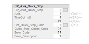
CIP_Axis_Quick_Stop AOI
Description
The CIP_Axis_Quick_Stop AOI requests to decelerate the AKD2G-SPI axis to a stop using the Quick Stop method via the CIP_Axis_State_Machine where the ramp and behavior used are defined by the AXIS#.EIP.QUICKSTOPACTION parameter setting. The primary usage is to decelerate to a stop while not streaming as in the case of homing (i.e., abort home move).
Compatibility
The CIP_Axis_Quick_Stop AOI is only compatible with AKD2G-SPI drives when used with Motion Supported PLCs with Studio 5000 and the CIP Sync connection.
Required Command Source and Operation Mode
AXIS#.CMDSOURCE = Fieldbus
AXIS#.OPMODE = Position
The CIP_Axis_Quick_Stop AOI passes a RequestedAction of 4 to the corresponding CIP_Axis_State_Machine AOI for the given axis.
There are four possible AXIS#.EIP.QUICKSTOPACTION values set by the user in WorkBench Terminal or via Explicit Messaging over EtherNet/IP communications.
-
The default value is 2 which uses the axis’ controlled stop and disable method. Values 1 and 2 use different deceleration parameters, but both quick stop actions disable the axis when the decel to stop is complete and the state is then transitioned to Switched On Disabled.
-
Values 5 and 6 use different deceleration parameters, but neither quick stop action disables the axis (stay enabled) when the decel to stop is complete and the state remains in the Quick Stop Active State. For Values 5 and 6 where the axis remains enabled and in the Quick Stop Active State, use the CIP_Axis_Enable AOI to transition from Quick Stop Active (and enabled) to Operation Enabled after executing the CIP_Axis_Quick_Stop AOI.
There are two possible cases in which the CIP_Axis_Quick_Stop is determined to be in process (IP) or process complete (PC).
-
When AXIS#.EIP.QUICKSTOPACTION = 1 or 2 the Axis.Status.Quick_Stop and Axis.Status.Switch_On_Disabled status bits in the axis’ status word determine when the CIP_Axis_Quick_Stop AOI is in process (IP) or completed (PC).
-
When AXIS#.EIP.QUICKSTOPACTION = 5 or 6 the Axis.Status.Quick_Stop and Axis.Status.Target_Reached status bits in the axis’ status word determine when the CIP_Axis_Quick_Stop AOI is in process (IP) or completed (PC).
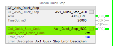
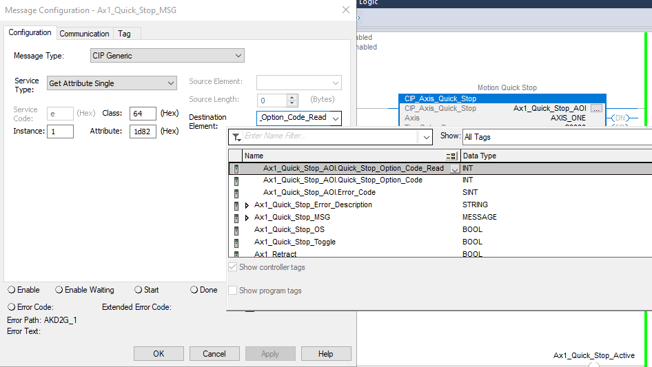
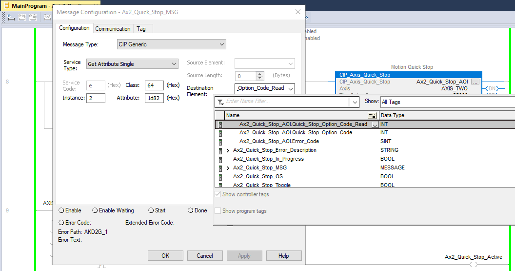
In order to determine which case (and set of status bits to use) it is necessary for the CIP_Axis_Quick_Stop to read the AXIS#.EIP.QUICKSTOPACTION value in the AKD2G drive via the MSG (message) instruction embedded in the CIP_Axis_Quick_Stop AOI. When the CIP_Axis_Quick_Stop is first enabled and executes it also executes the MSG instruction to read the AXIS#.EIP.QUICKSTOPACTION value and then displays the value read in the Quick_Stop_Option_Code field of the CIP_Axis_Quick_Stop AOI as shown in the following figure.
Get_Quick_Stop_Code MSG Setup Guidelines
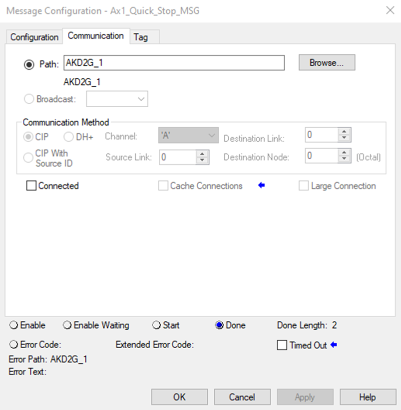
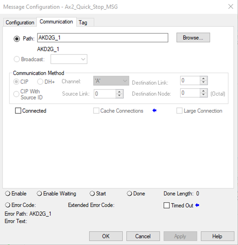
From the Sample project the following MSGs are configured for Axis 1 and Axis 2 respectively.
Axis 1:
Message Configuration:
Message Type: CIP Generic
Service Type: Get Attribute Single
Service Code: e
Class: 64
Instance: 1 (Axis 1)
Attribute: 1d82 (hex)
Destination Element: Tag that points to CIP_Axis_Quick_Stop instance Name.Quick_Stop_Option_Code_Read (Example: Ax1_Quick_Stop_AOI.Quick_Stop_Option_Code_Read)
| ID | Instance | Attribute | Name | Data Type | Access | User Mappable |
|---|---|---|---|---|---|---|
| 7554 | 1 | 0x1d82 | AXIS1.EIP.QUICKSTOPACTION | Signed16 | Read/Write | Yes |
Axis 2:
Message Configuration:
Message Type: CIP Generic
Service Type: Get Attribute Single
Service Code: e
Class: 64
Instance: 2 (Axis 2)
Attribute: 1d82 (hex)
Destination Element: Tag that points to CIP_Axis_Quick_Stop instance Name.Quick_Stop_Option_Code_Read (using the example above, Ax2_Quick_Stop_AOI.Quick_Stop_Option_Code_Read)
| ID | Instance | Attribute | Name | Data Type | Access | User Mappable |
|---|---|---|---|---|---|---|
| 73090 | 2 | 0x1d82 | AXIS2.EIP.QUICKSTOPACTION | Signed16 | Read/Write | Yes |
The CIP_Axis_Quick_Stop AOI has multiple possible error conditions which are described in the Execution and Troubleshooting section of this topic.
The CIP_Axis_Quick_Stop instruction execution time may require multiple scans due to the required fieldbus communication time and is also time dependent on the settings of the controlled stop (set in WorkBench on the Axis 1 or Axis 2 Enable/Disable view) or the AXIS#.FBUS.DEC depending on the AXIS#.EIP.QUICKSTOPACTION value is configured in the AKD2G drive.
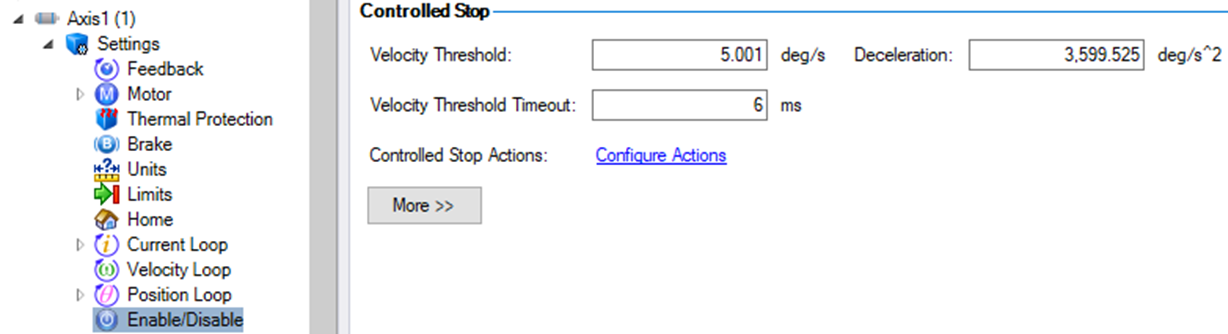
Figure 1: Example: Axis 1 Control Stop settings shown.
Operands
These entries are required by the user.
|
Operand |
Data Type |
Format |
Description |
|---|---|---|---|
|
Operand |
Data Type |
Format |
Description |
|
CIP_Axis_Quick_Stop |
CIP_Axis_Quick_Stop |
Tag |
Tag name for instance of the AOI. |
|
Axis |
CIP_Axis |
Tag |
User tag defined in the Axis1 or Axis2 field of the CIP_Drive_Comms AOI. |
|
Timeout_mS |
DINT |
Generally a Constant value, but Tag is possible. |
Constant value or user tag for a defined user timeout to declare the CIP_Axis_Quick_Stop AOI took too long to complete. A |
|
Get_Quick_Stop_Code |
MESSAGE |
Tag |
See From the Sample project . |
|
Error_Description |
STRING |
Tag |
User tag to display the string error code description. In run-time when the mouse cursor is hovered over the tag the string can be monitored. If Error_Code is:
|
Structure
These fields are not entered by the user and are populated automatically with Read Only data once the Operands (in the Operand table for this AOI) are entered or presented as output data (bits).
|
Mnemonic |
Type |
Format |
Description |
|---|---|---|---|
|
.EnableIn |
Input |
BOOL |
The Enable Input bit indicates the instruction is enabled. |
|
.EnableOut |
Output |
BOOL |
The Enable Output bit is the output of the Enable Input (.EnableIn) bit. |
|
.DN |
Output |
BOOL |
Set when Axis.Status.Quick_Stop bit turns OFF (Quick Stop in progress). |
|
.ER |
Output |
BOOL |
The .ER bit is set when any of the 6 error conditions are present. |
| .IP | Output | BOOL | See IP and PC Bit Behavior table. |
| .PC | Output | BOOL | See IP and PC Bit Behavior table. |
|
Quick_Stop_Option_Code |
Input |
INT |
Displays the value of the AXIS#.EIP.QUICKSTOPACTION parameter in the AKD2G drive for the given axis. Read by the internal MSG of the CIP_Axis_Quick_Stop AOI. See AXIS#.EIP.QUICKSTOPACTION for more details. |
|
Error_Code |
Output |
SINT |
If Error_Code is:
|
| Quick Stop Option Code Read |
Axis.Status.Quick_Stop | Axis.Status.Switched_On_Disabled | IP bit | PC bit |
|---|---|---|---|---|
|
1 or 2 |
0 |
0 |
ON |
OFF |
|
1 or 2 |
0 |
1 |
OFF |
ON |
| Quick Stop Option Code Read |
Axis.Status.Quick_Stop | Axis.Status.Target_Reached | IP bit | PC bit |
|---|---|---|---|---|
|
5 or 6 |
0 |
0 |
ON |
OFF |
|
5 or 6 |
0 |
1 |
OFF |
ON |
Changes to Axis Status Bits and Control Word Bits Description
- All status bits are updated from the drive.
- See Status Word in CIP Sync Response Assembly Data Structure (106).
- Control Word bits descriptions and functions are described under Control Word in CIP Sync Command Assembly Data Structure (105).
- See CIP Sync: State Machine.
On Quick Stop success, depending on the AXIS#.EIP.QUICKSTOPACTION setting, the status bits are as follows:
-
Quick Stop Action Code = 1 or 2
After Quick Stop axis state machine goes to Switched On Disabled-
While Quick Stop Active:
Bit Name Status 5 Quick Stop OFF - When Quick Stop deceleration completes and axis state machine transitions to Switched On Disabled state:
Bit Name Status 0 Ready To Switch On OFF 1 Switched On OFF 2 Operation Enabled OFF 6 Switched on Disabled ON
-
- Quick Stop Action Code = 5 or 6
After Quick Stop axis state machine stays in Quick Stop Active State and axis remains enabled -
While Quick Stop Active:
Bit Name Status 5 Quick Stop OFF When Quick Stop deceleration completes the axis stays enabled and in the Quick Stop Active State.
- No changes to the following bit states:
Bit Name Status 0 Ready To Switch On ON 1 Switched On ON 2 Operation Enabled ON
Example of Usage/Programming Guidelines
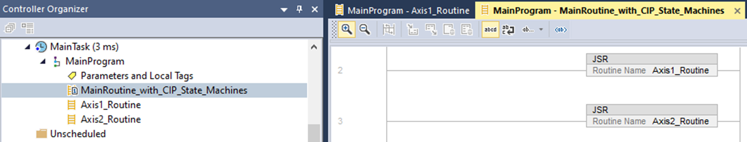
In the Sample project the CIP_Axis_Quick_StopAOI is used in the subroutine for the given axis under MainTask → MainProgram → Axis1_Routine or Axis2_Routine.
Subroutines are called in the MainRoutine_with_CIP_State_Machines routine under MainTask → Main Program.
The best practice for the CIP_Axis_Quick_Stop AOI is to use a conditional N.O. Contact as a trigger (Ax1_Quick_Stop_Toggle in the example) and then use a One Shot (ONS) to trigger the CIP_Axis_Quick_Stop AOI.EnableIn. A parallel branch is implemented around the N.O. Contact and One Shot to seal-in the .EnableIn of the AOI until execution completes (.PC; Success) or fails (.ER; Error). The AXIS_ONE.Status.Quick_Stop status bit as a N.O. Contact is used as an interlock to ensure the CIP_Axis_Quick_Stop AOI cannot be triggered if the axis is already in the Quick Stop Active State.
Depending on the AXIS#.EIP.QUICKSTOPACTION setting, the deceleration or controlled stop ramp and settings selected by the user will affect how long the quick stop takes to complete. The CIP_Axis_Quick_Stop AOI’s TimeOut_mS field allows the user to set a time limit on how long the CIP_Axis_Quick_Stop AOI takes to complete (success) before timing out and declaring a timeout error.
An additional rung provides a way to monitor the Quick Stop Active state in the ladder based on the Quick Stop Active State using status bits in the Status Word. See table States of the State Machine in CIP Sync: State Machine.
| State | Bit 6 Switch on Disabled | Bit 5 Quick Stop | Bit 3 Fault | Bit 2 Operation Enabled | Bit 1 Switched On | Bit 0 Ready to Switch On |
|---|---|---|---|---|---|---|
|
Quick stop active |
0 |
0 |
0 |
1 |
1 |
1 |
Quick Stop Active is True and the Ax1_Quick_Stop_Active coil turns ON when the following criteria are met:
-
AXIS_ONE.Status.Ready_To_Switch_On is ON
-
AXIS_ONE.Status.Switched_On is ON
-
AXIS_ONE.Status.Operation_Enabled is ON
-
AXIS_ONE.Status.Fault is OFF
-
AXIS_ONE.Status.Quick_Stop is OFF
-
AXIS_ONE.Status.Switch_On_Disabled is OFF
AXIS_ONE is the name given to Axis1 in the CIP_Drive_Comms as an alias for all other Kollmorgen CIP_Axis AOIs to use for that axis.
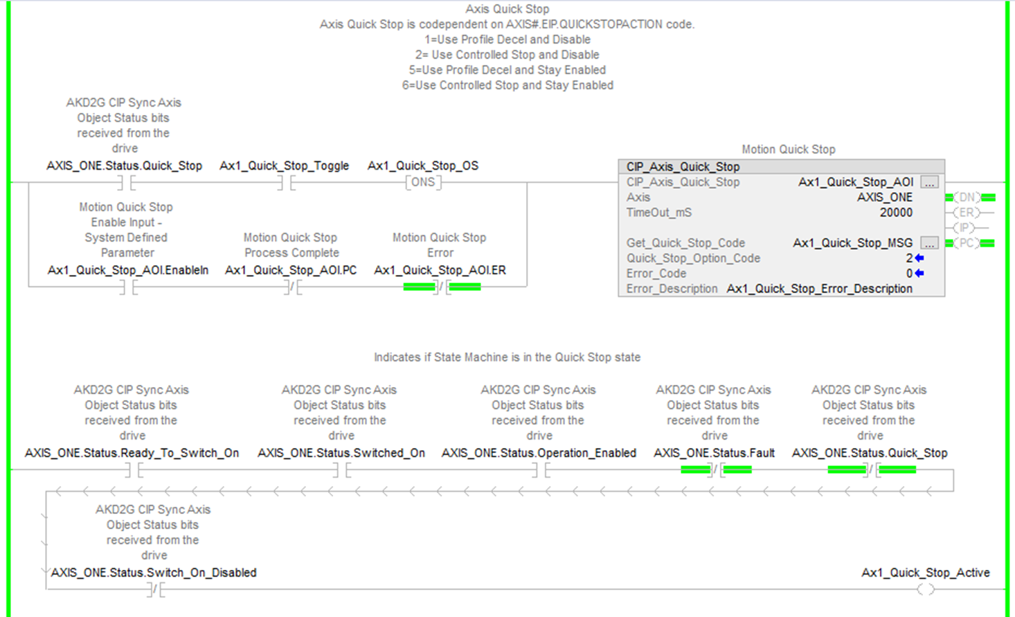
Figure 2: Example: Axis1_Routine with CIP_Axis_Quick_Stop AOI
As previously noted, for AXIS#.EIP.QUICKSTOPACTION values 5 and 6 where the axis remains enabled and in the Quick Stop Active State use the CIP_Axis_Enable AOI to transition from bit 5 Quick Stop Active (and enabled) to bit 2 Operation Enabled.
Troubleshooting
The possible conditions for the Error (.ER) bit to be set for the CIP_Axis_Home AOI:
- Axis.Status.Fault is ON (Axis Faulted).
- Set the Error_Code = 2
- Set Error_Description = Axis Faulted
- Axis.Status.Fault is OFF (Axis not Faulted) but Get_Quick_Stop_Code MSG instruction errored (failed to read).
- Set the Error_Code = 3
- Set the Error_Description = Get Quick Stop MSG Error
- Axis.Status.Fault is OFF (Axis not Faulted), but the Command_Timeout timer expired before the Axis.Status.Quick_Stop status bit turned OFF (indicating the command to quick stop was not acknowledged and failed).
- Set the Error_Code = 1
- Set the Error_Description = Command Timeout
- Step Number = 3 (IP, in process) TimeOut timer timed out indicating the required status bit states did not confirm the Quick Stop successfully completed before the TimeOut in msec.
- Set the Error_Code = 5
- Set the Error_Description = Quick Stop Timeout_mS Exceeded
- Axis.Status.Fault is OFF (Axis not Faulted) and the Get_Quick_Stop_Code MSG is DN (read successful) but the value read is not equal to 1, 2, 5, or 6.
- Set the Error_Code = 4
- Set the Error_Description = Axis Quick Stop Code Not 1, 2, 5, or 6
Step Summary
|
Step Number |
Operation/Result |
|---|---|
|
0 |
|
|
1 |
Set the Axis.RequestedAction to 4 (Quick Stop) and set the Step Number to 2. |
|
2 |
After Command_Delay, check for Axis.Status.Quick_Stop (to turn OFF via the CIP_Axis_State_Machine AOI). If success turn ON the .DN bit of the CIP_Axis_Quick_Stop AOI and set Step Number to 3. If Axis.Status.Quick_Stop does not turn OFF by the Command_Timeout (5000 msec) an error will be declared. |
|
3 |
|
|
-1 |
Error (See Troubleshooting above for details.) |
Revision History
| Revision Number | Description/Notes | Date of Revision |
|---|---|---|
| v1.5 | Initial release | 03-14-2024 |