


STO (Safe Torque Off)
Safe Torque Off description for drive option Functional Safety 1.
STO is suited for SIL 2 according to IEC 62061 and PLd / Cat.3 according to ISO 13849-1. It is a type A subsystem according to IEC 61508.
This safety function turns off the drive output stage that powers the motor and corresponds to an uncontrolled stop according to IEC 60204-1, category 0.
Important Notes
|
|
The safety properties given in this documentation refer to the device AKD2G with functional safety option 1. |

|
|
Serious injury could result when a suspended load is not properly blocked. The drive cannot hold a vertical load when STO is active.
|


Activation
The digital STO inputs (channel A and B) must be connected to the output of a safety device, which at least meets the requirements of PLd, Cat. 3 according to ISO 13849. Technical data of the safe inputs (see "Technical Data").
If one of the STO inputs goes open-circuit or 0V, then power supply to the servo motor stops within
If the servo drive detects that the two STO inputs are in a different state for longer than
|
|
Review the enclosure and wiring instructions (see "Enclosure, wiring"). |

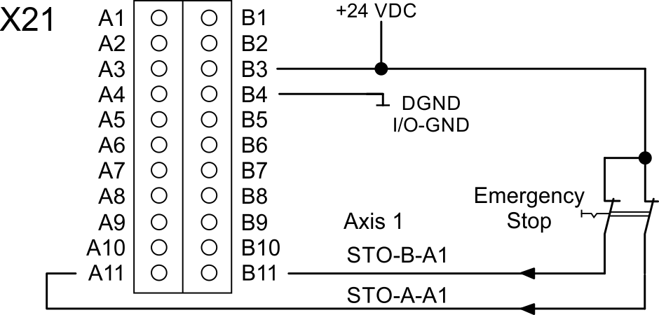
Wiring example STO single axis, SIL2/PLd, Emergency Stop
Note: AXIS#.SAFE.STO.REPORTFAULT should be set to 1 if STO is activated by a switch.
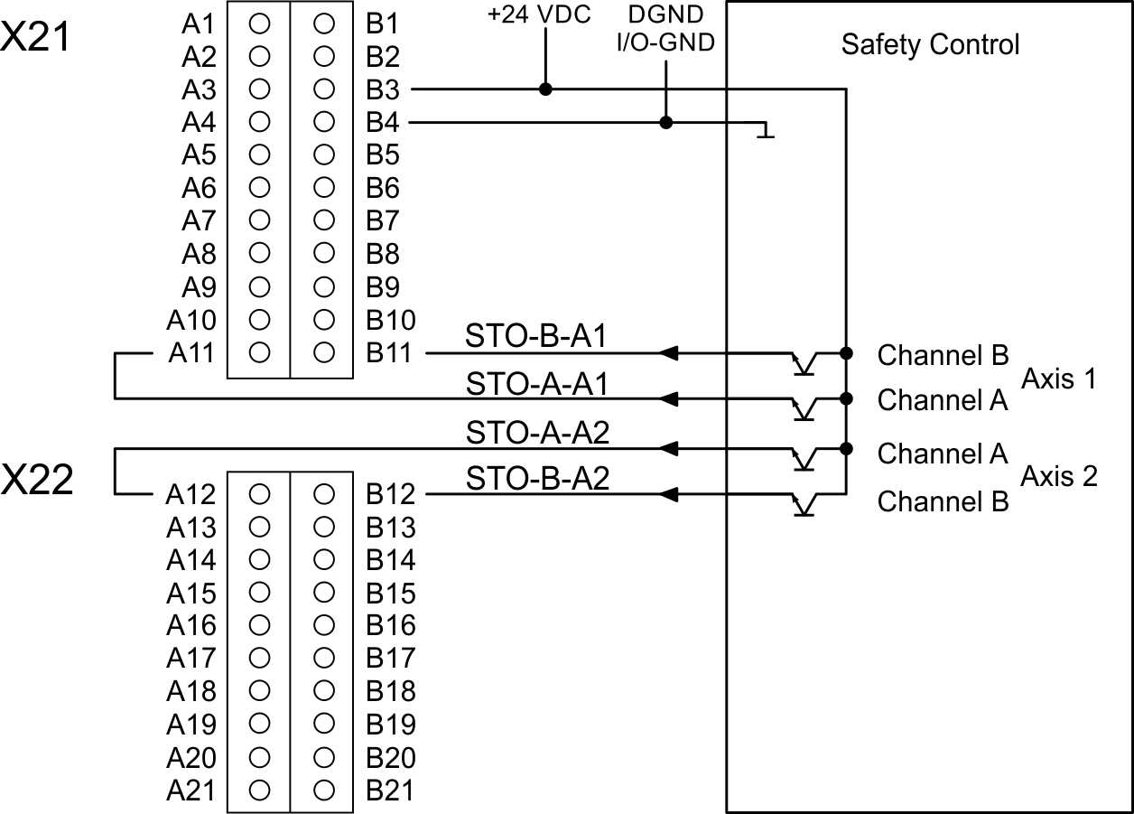
Wiring example STO dual axis, SIL2/PLd, Safety Control
Restart
|
AXIS1.SAFE.STO. |
AXIS1.SAFE.STO. |
|
|---|---|---|
|
Example 1: |
Message W9000 Restart:
|
Restart:
|
|
Example 2: |
Messages W9000 and F9000 Restart:
|
Restart:
|
|
Example 3: |
Message F9005 Restart:
|
Message F9005 Restart:
|
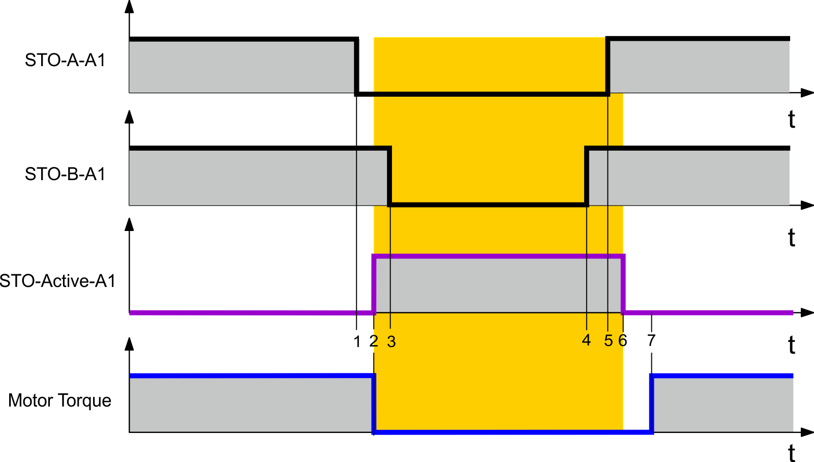
Timing
Example
|
Timing |
max |
Remarks |
|---|---|---|
|
t1 |
STO channel A enabled (0 V) |
|
|
t1 to t2 |
2ms |
STO enable delay (response time) |
|
t2 |
STO active |
|
|
t3 |
STO channel B enabled (0 V) |
|
|
t1 to t3 |
100ms |
accepted delay between dual channel edges |
|
t4 |
STO channel B disabled (+24 V) |
|
|
t5 |
STO channel A disabled (+24 V) |
|
|
t4 to t5 |
100ms |
accepted delay between dual channel edges |
|
t5 to t6 |
2ms |
STO release delay |
|
t6 |
STO release |
|
|
t6 to t7 |
Zero if AXIS#.SAFE.STO.REPORTFAULT=0 |
|
|
t7 |
|
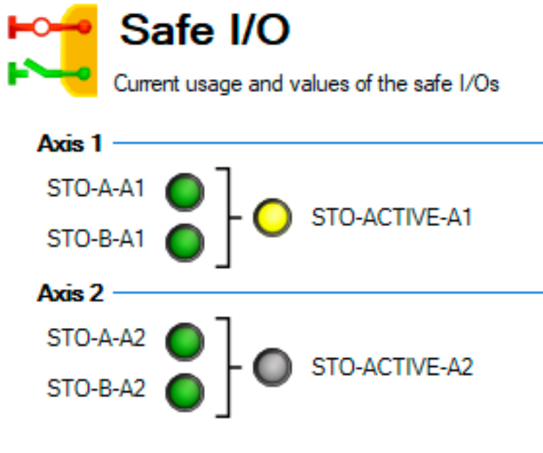
Safety Diagnostic view in WorkBench
The WorkBench view "Safety Diagnostic" shows the current status on the safe inputs (AXIS#.SAFE.STO.A / AXIS#.SAFE.STO.B) and the logical status of the STO function for
Fault Reaction / Failure Messages
With the dual-channel control of the STO (SIL2/PLd Cat.3) safety function, the switch-off paths STO-A-A# and STO-B-A# are switched separately by two outputs of a safety controller.
W9000 and F9000 are conditioned by the value of AXIS#.SAFE.STO.REPORTFAULT.
AXIS#.SAFE.STO.REPORTFAULT set to 1 (default)
|
STO-A-A# |
STO-B-A# |
ENABLE |
Drive |
Motor |
Safe State |
|---|---|---|---|---|---|
|
0 V |
0 V |
0 V |
W9000 |
No |
Yes |
|
0 V |
0 V |
+24 V |
F9000 |
No |
Yes |
|
+24 V |
+24 V |
0 V |
- |
No |
No |
|
+24 V |
+24 V |
+24 V |
- |
Yes |
No |
|
+24 V |
0 V |
0 V |
F9005* |
No |
Yes |
|
+24 V |
0 V |
+24 V |
F9005* |
No |
Yes |
|
0 V |
+24 V |
0 V |
F9005* |
No |
Yes |
|
0 V |
+24 V |
+24 V |
F9005* |
No |
Yes |
* different status of STO-A/B for more than 100ms
A#: A1 for axis 1
AXIS#.SAFE.STO.REPORTFAULT set to 0
|
STO-A-A# |
STO-B-A# |
ENABLE |
Drive |
Motor |
Safe State |
|---|---|---|---|---|---|
|
0 V |
0 V |
0 V |
W9000 |
No |
Yes |
|
0 V |
0 V |
+24 V |
W9000 |
No |
Yes |
|
+24 V |
+24 V |
0 V |
- |
No |
No |
|
+24 V |
+24 V |
+24 V |
- |
Yes |
No |
|
+24 V |
0 V |
0 V |
F9005* |
No |
Yes |
|
+24 V |
0 V |
+24 V |
F9005* |
No |
Yes |
|
0 V |
+24 V |
0 V |
F9005* |
No |
Yes |
|
0 V |
+24 V |
+24 V |
F9005* |
No |
Yes |
* different status of STO-A/B for more than 100ms
A#: A1 for axis 1


