


SDB (Safe Dynamic Brake)
Safe Dynamic Brake description for drive option Functional Safety 2 or 3.
Description
If the motor brake allows standstill braking only, dynamic braking is a method to slow down a servo system by dissipating the mechanical energy driven by the motor back EMF. When activated, the optional external Safe Dynamic Brake Contactor shortens the motor terminals. This forces all of the dynamic braking current to be stopping current. While the lines to the motor are shorted, the SDB status signal will be applied. When configured, SDB gets executed simultaneously along with STO.
Use this function when operating with high inertia loads.
Important Notes
|
|
Serious injury could result when the load is not properly blocked. This function does not ensure functional safety.
|
||
|
|
|


Function Input / Output Variables
Inputs
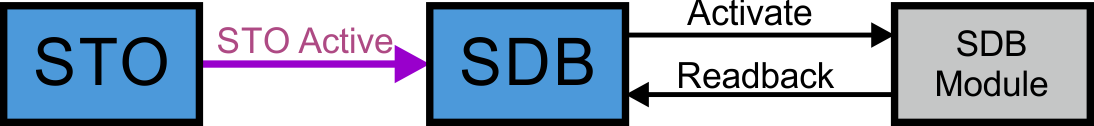
- STO Active: refer to (➜ # 1, STO (Safe Torque Off))
- SDB Readback: input for diagnosis signal returning from the SDB-Contactor
Outputs
- SDB Activate: signal for activating the SDB-Contactor auxiliary contacts
Number of Instances
One instance per axis.
Activation
SDB can be configured to be activated during the STO process. The SDB-Contactor function must be supervised using the status path. AKD2G can supply a signal with OSSD pulses to the SDB-Contactor (set SOUTx to "ON") for diagnosis. This OSSD signal can also be provided by the safe PLC. The SDB-Contactor output status is evaluated by the drive. Use SDB.READBACKSOURCE for mapping the safe input to the SDB status signal.
|
|
The used SDB-Contactor must have a freewheeling diode in parallel to the coil. The braking energy can be limited using external resistors (Rext) limiting the back EMF current. Contact Kollmorgen Technical support for usable SDB-Contactors or component sizing. |
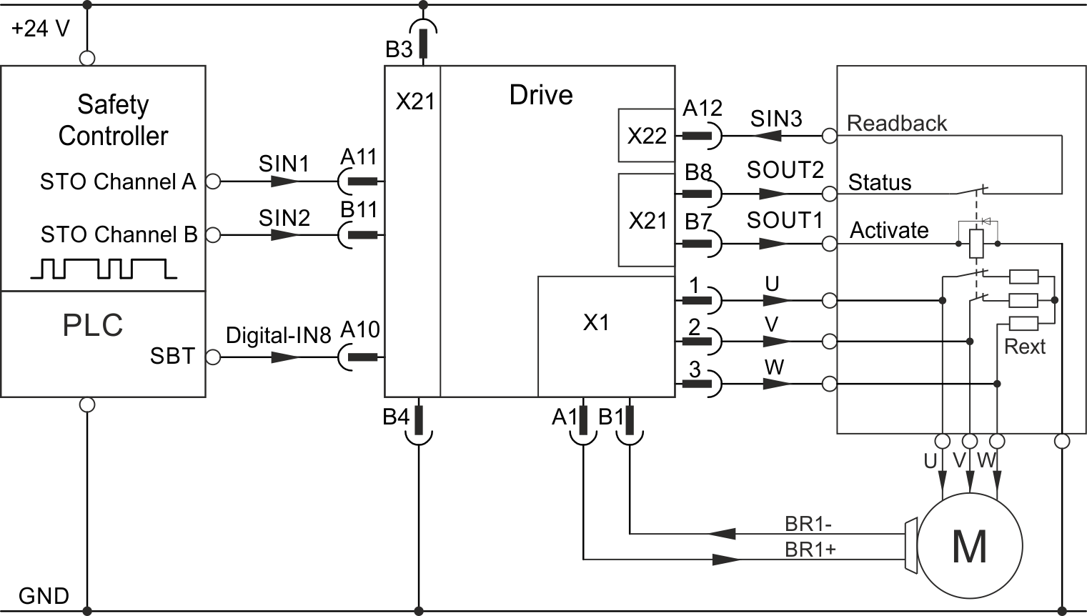
Example: STO activated by safe inputs, SDB single channel, SIL2 PLd, SBC, SBT
Setting : SOUT1 = Activate SDB, SOUT2 = on, SIN3 = Readbacksource
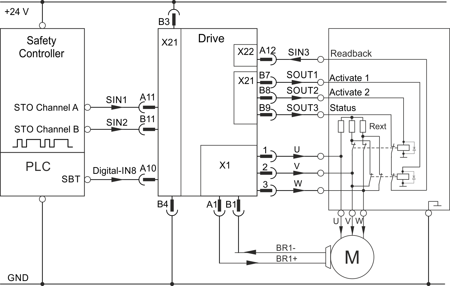
Example: STO activated by safe inputs, SDB dual channel, SIL3 PLe, SBC, SBT
Setting : SOUT1 = Activate SDB channel 1, SOUT2 = Activate SDB channel 2,
SOUT3 = on, SIN3 = Readbacksource
Restart
Refer to STO for restart conditions (➜ # 1, Restart). When all conditions for a STO restart are fulfilled and SDB is configured, the SDB-Contactor will be deactivated and the readback diagnosis will be disabled. After the configured delay (same as during SDB activation) the STO will disable, allowing torque. The readback diagnosis will reengage after the configured time.
Timing
SMM 1.04

SMM R_02-07-000/SMM R_03-00-003

| SMM 1.04 | SMM R_02-07-000/SMM R_03-00-003 | |||
|---|---|---|---|---|
|
Timing |
Max. |
Remarks |
Max. |
Remarks |
|
t1 to t2 |
< 6 ms |
STO response time |
< 6 ms |
STO response time |
|
t1 to t3 |
configurable |
tSDB: Delay before switching SDB-Contactor |
fixed |
Delay of 6ms |
|
t3 to t4 |
see datasheet |
Mechanical delay SDB-Contactor |
see datasheet |
Mechanical delay SDB-Contactor |
|
t3 to t5 |
configurable |
t_D_SDB:Delay until readback diagnosis |
configurable |
t_D_SDB:Delay until readback diagnosis |
|
t6 to t7 |
configurable |
tSDB: Max. delay for SDB-Contactor to switch |
see datasheet |
Mechanical delay SDB-Contactor |
|
t6 to t8 |
configurable |
t_D_SDB: Delay until readback diagnosis |
configurable |
t_D_SDB: Delay until readback diagnosis |
Related Parameters
| SMM 1.04 | |||
|---|---|---|---|
|
Name |
Variables |
Default |
Parameter |
|
Function Activation |
- |
0 (Never active) |
|
|
Readback |
- |
Not Used |
|
|
Delay Before Switching |
tSDB |
1 ms |
|
|
Delay Before Diagnose |
t_D_SDB |
1 ms |
|
| SMM R_02-07-000/SMM R_03-00-003 | |||
|---|---|---|---|
|
Name |
Variables |
Default |
Parameter |
|
Function Activation |
- |
0 (Never active) |
|
|
Readback |
- |
Not Used |
|
|
Delay Before Diagnose |
t_D_SDB |
1 ms |
|
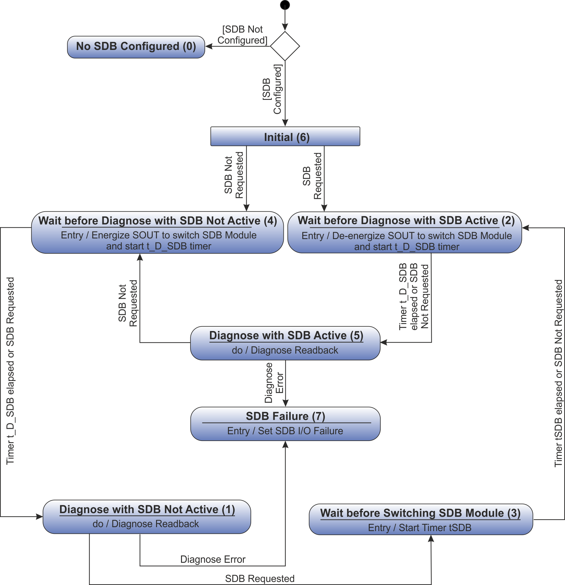
State Diagram
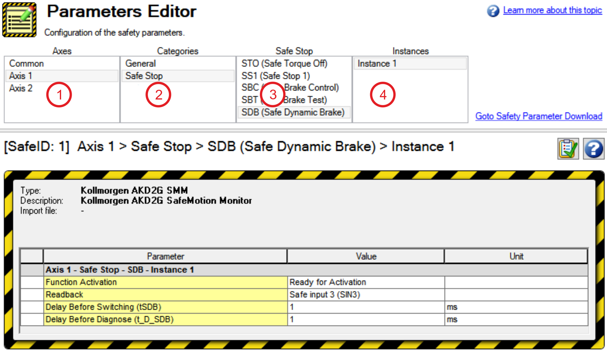
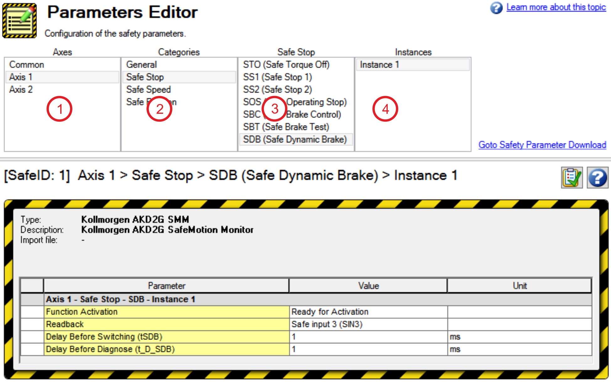
Setup in WorkBench
Select Safety Parameterization view (see "WorkBench Safety Function Setup").
Choose the axis (1), category (2) and SDB function (3).
Fault Reaction / Failure Messages
The drive supervises the safe input(s) assigned as readback. An OSSD pulsed signal, either from a safe output or a safe PLC, is required. When the readback signal becomes static, an I/O error will be detected.
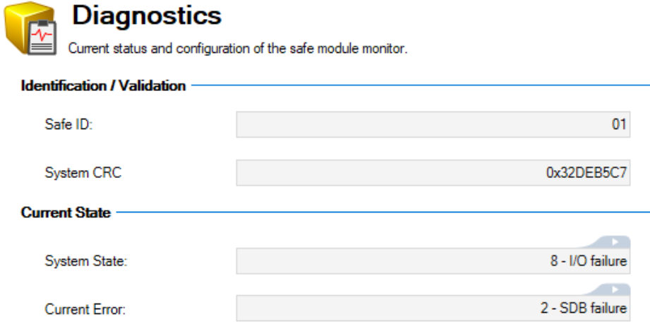
During the activation and deactivation of the SDB function, the readback diagnosis will be interrupted for the parameterized amount of time. When STO/SDB are active, a high signal (24V) is expected. When STO/SDB are not active, a low signal (0V) is expected. Deviating this expected behavior will additionally result in a SDB failure recognizable from the diagnostics view.
For detailed information on the signal states refer to Timing.
Safety State / Status Signals
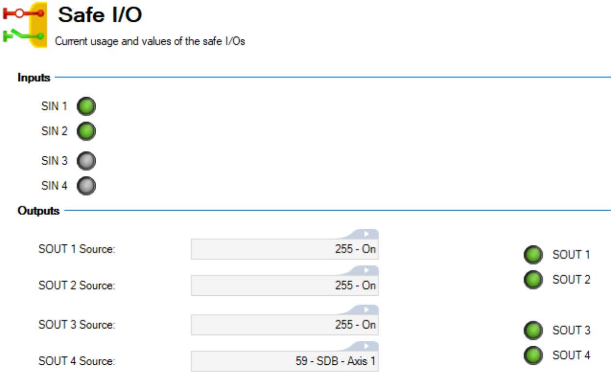
The WorkBench view “Safety Diagnostics – Safe I/O” shows the current status off the safe inputs and outputs.
The target status can be read of the assigned output(s). The status of the SDB readback can be read from the assigned input(s). Which state is appropriate depends on the system state.
For detailed information on the signal states refer to Timing.
Safety Properties
Refer to (➜ # 1, Safety Properties Overview).


