


SBC (Safe Brake Control)
Safe Brake Control description for drive option Functional Safety 2 or 3.
Description
The safety function SBC (Safe Brake Control) is used for controlling the brakes wired to X1, X2 or X4 of the AKD2G. The connected brake is engaged and released by switching both lines (BR+ and BR-).
- The safety function SBC makes a motor with a motor brake suitable for the usage scenarios A1, A2, E1, E2, E3 according to DGUV.
- The safety function SBC makes a motor with a motor brake and a second brake on the same axis suitable for the usage scenarios A1, A2, A3, E1, E2, E3 according to DGUV.
- The brake can be configured with or without (➜ # 1, SDB (Safe Dynamic Brake)).
- For requirements to the motor brakes refer to (➜ # 1, Motor Brake Requirements ).
Association of brake outputs to drive axes
| Drive Type | Brake 1 | Brake 2 | max. SBC Safety Level |
|---|---|---|---|
|
Single Axis |
Axis 1 (X1) |
Axis 1 (X4) |
Axis 1 : SIL3 / PLe |
|
Single Axis |
Axis 1 (X1) |
Not used |
Axis 1 : SIL2 / PLd |
|
Single Axis |
Not used |
Axis 1 (X1) |
Axis 1 : SIL2 / PLd |
|
Dual Axes |
Axis 1 (X1) |
Axis 2 (X2) |
Axis 1 : SIL2 / PLd |
|
Dual Axes |
Axis 1 (X1) |
Axis 1 (X2) |
Axis 1 : SIL3 / PLe |
|
|
To achieve SIL 3 / PLe for SBC,
|

Important Notes
|
|
Hoist and crane support: The drive will safely ensure a holding position, as long as SBC (braking ramp, delay time) is configured correctly.
|
|
|
For requirements to the motor brakes refer to Motor Brake Requirements . |

Function Input / Output Variables
Inputs
- SBC Delay: brake delay tSBC
- SBC Muting:
- can be used for enabling manual override of the brakes while STO is active.
- muting can be activated by FSoE or safe digital inputs (must be mapped).
- SBC Activate:
- can be triggered by STO only without delay.
- the trigger with delay depends on the configuration, with/without SDB.
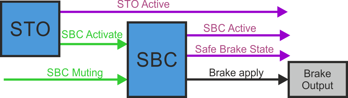
Outputs
- SBC Active: logical status of the SBC function
- Safe Brake State: state of the brake outputs (24V or 0V)
Number of Instances
One instance per axis.
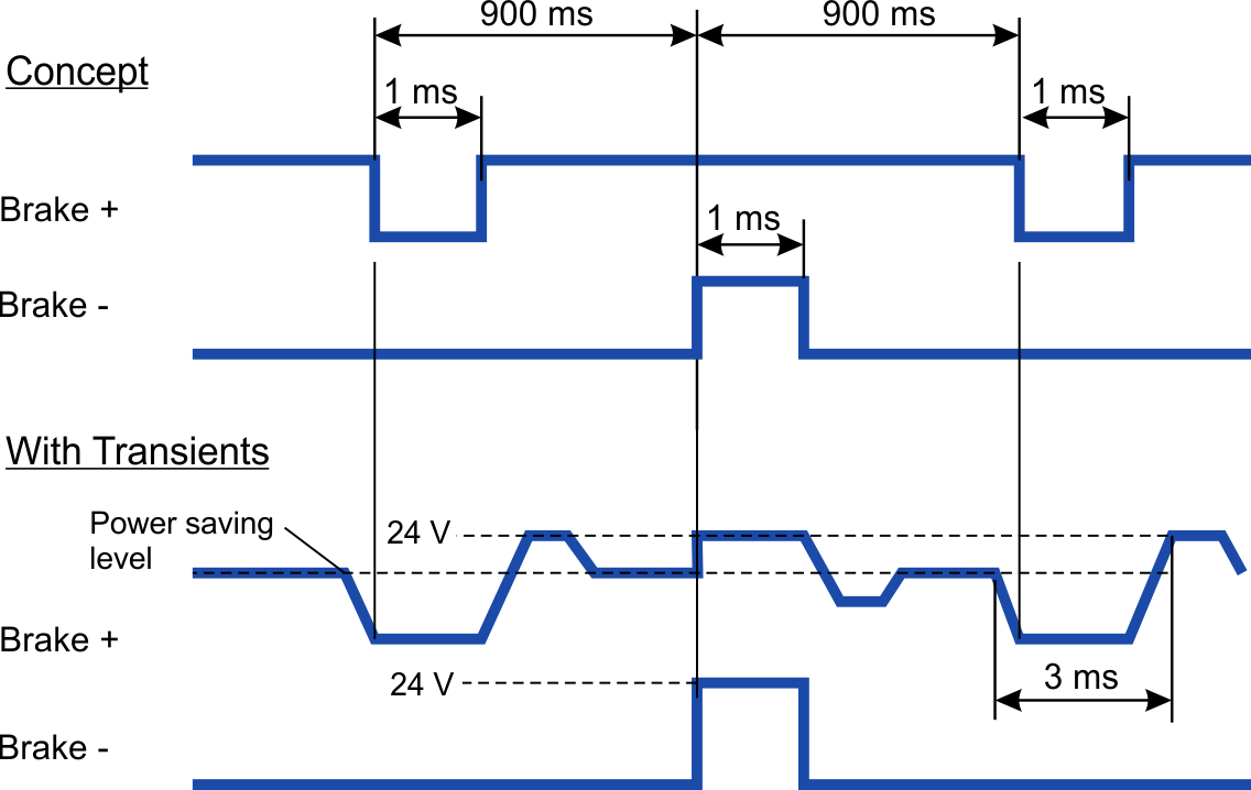
Test Pulses
Test pulses are applied to the Brake+ and Brake- outputs (X1, X2, X4) alternately to ensure valid feedback. The test pulses are 1ms at the bottom but are 3ms long due to their slow edges.
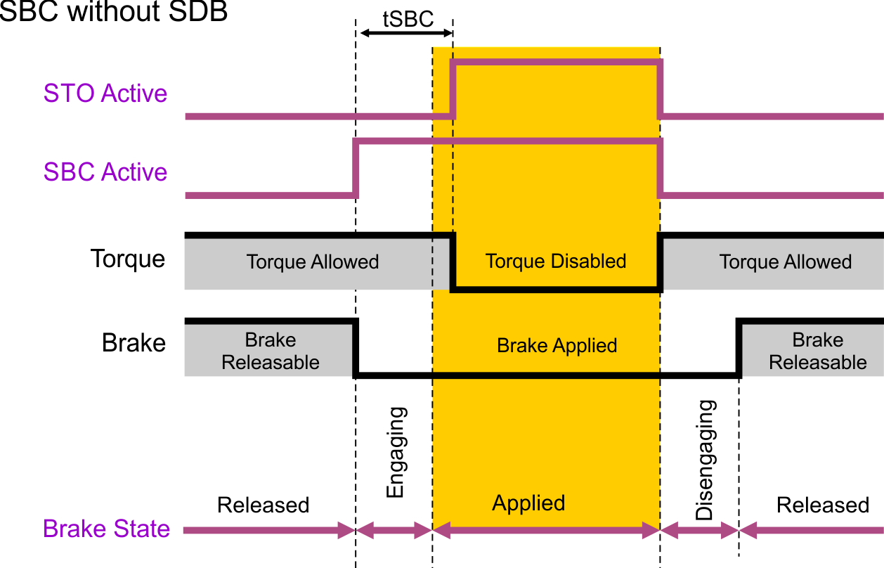
Activation
SBC for one or two brakes can be configured to be activated during STO process.
The controlled brake(s) can be configured to be engaged while motor torque is available (STO not active yet) or with STO became active (no motor torque).
|
|
The safety function can be configured with WorkBench or via FSoE. |
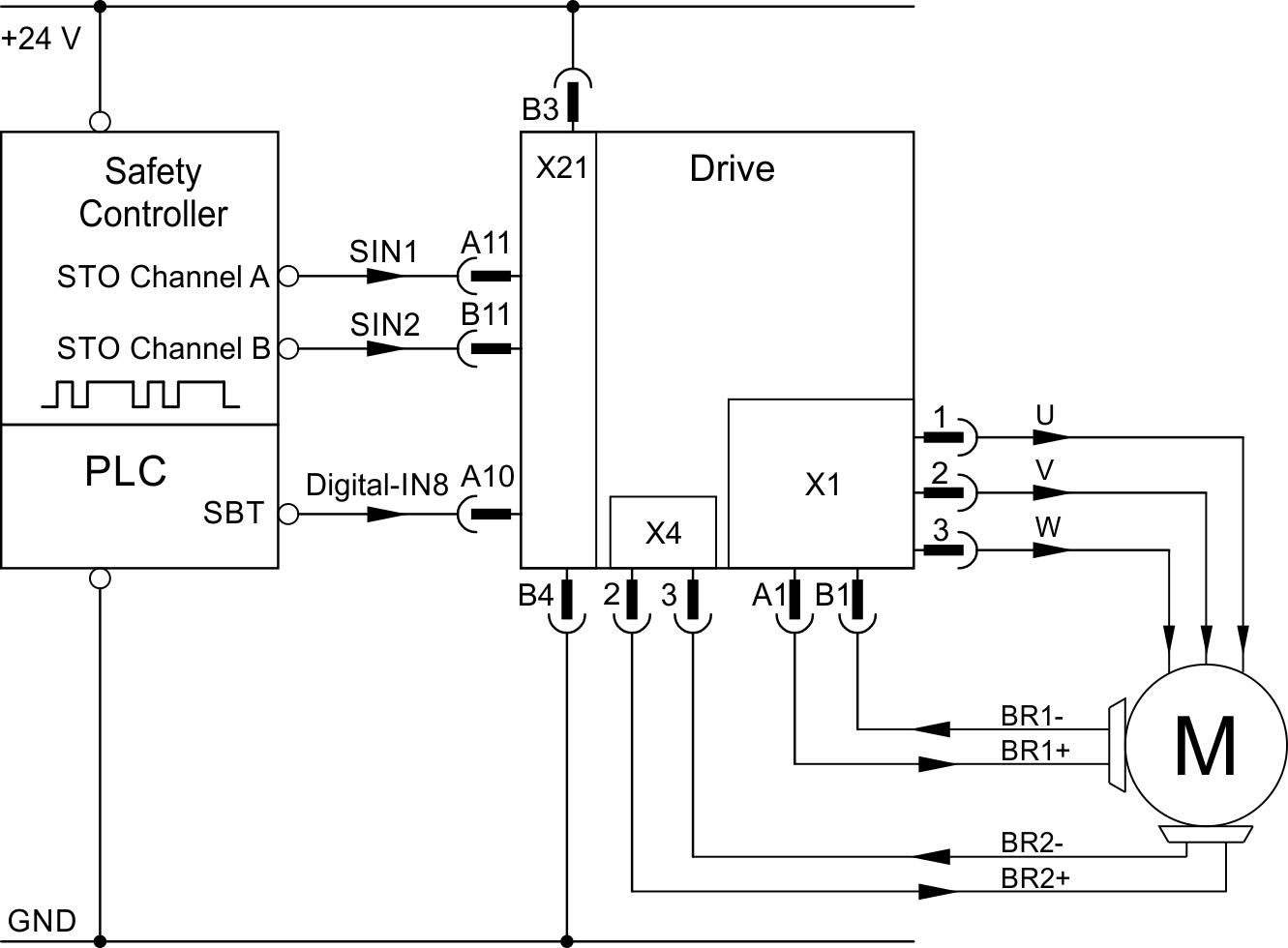
Example
STO activated by safe digital inputs, one axis, SIL3 PLe, SBC with two brakes, SBT, without SDB
Restart
The brakes controlled by SBC will disengage simultaneously with the deactivation of STO if AXIS#.SAFE.STO.REPORTFAULT is set to 0.
If AXIS#.SAFE.STO.REPORTFAULT is set to 1, the brake will release when the axis is enabled again. See STO Timing.
SBC Muting Function
|
|
SBC muting is critical with regards to safety and has important influence on the safety level of an application. It has to be ensured that the use of SBC muting has no negative impact on the required safety level within the complete operational range of the application. The reliability has to be independent from the application. |
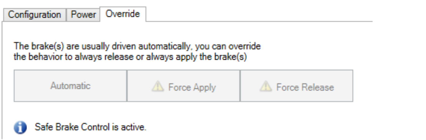
For servicing purposes, manual control of the brakes may be necessary.
When SBC muting is active, the brakes can be overwritten even if STO/SBC is active. The SBC active signal will be suppressed and manual control via WorkBench, digital input or EtherCAT is possible.
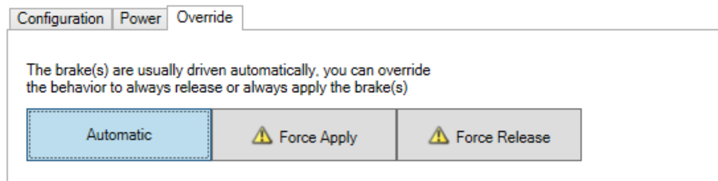
Manual control of the brakes is prohibited when SBC muting is not active and STO/SBC is active at the same time.
|
|
Overwriting the brake(s) behavior may create unsafe situations and/or damage. If the axis is used for a vertical load, forcing the brake(s) to release may damage the load.
|
If SBC Muting is active during STO activation and brake control is set to "automatic", brake behavior is determined by standard brake parameters.
Safety parameters
| Name | Variables |
Default |
Parameter |
|---|---|---|---|
|
SBC Brake 1 |
- |
0 |
|
|
SBC Brake 2 |
- |
0 |
|
|
Brake Delay |
tSBC |
100 ms |
|
|
SBC Muting |
- |
0 |
Diagnostic parameters
|
Name |
Variables |
Default |
Parameter |
|---|---|---|---|
|
Function Active Status |
- |
- |
|
|
Safe Brake State |
- |
- |
Device parameters
|
Name |
|
||
|---|---|---|---|
|
For device parameters refer to WorkBench online help. |
|||
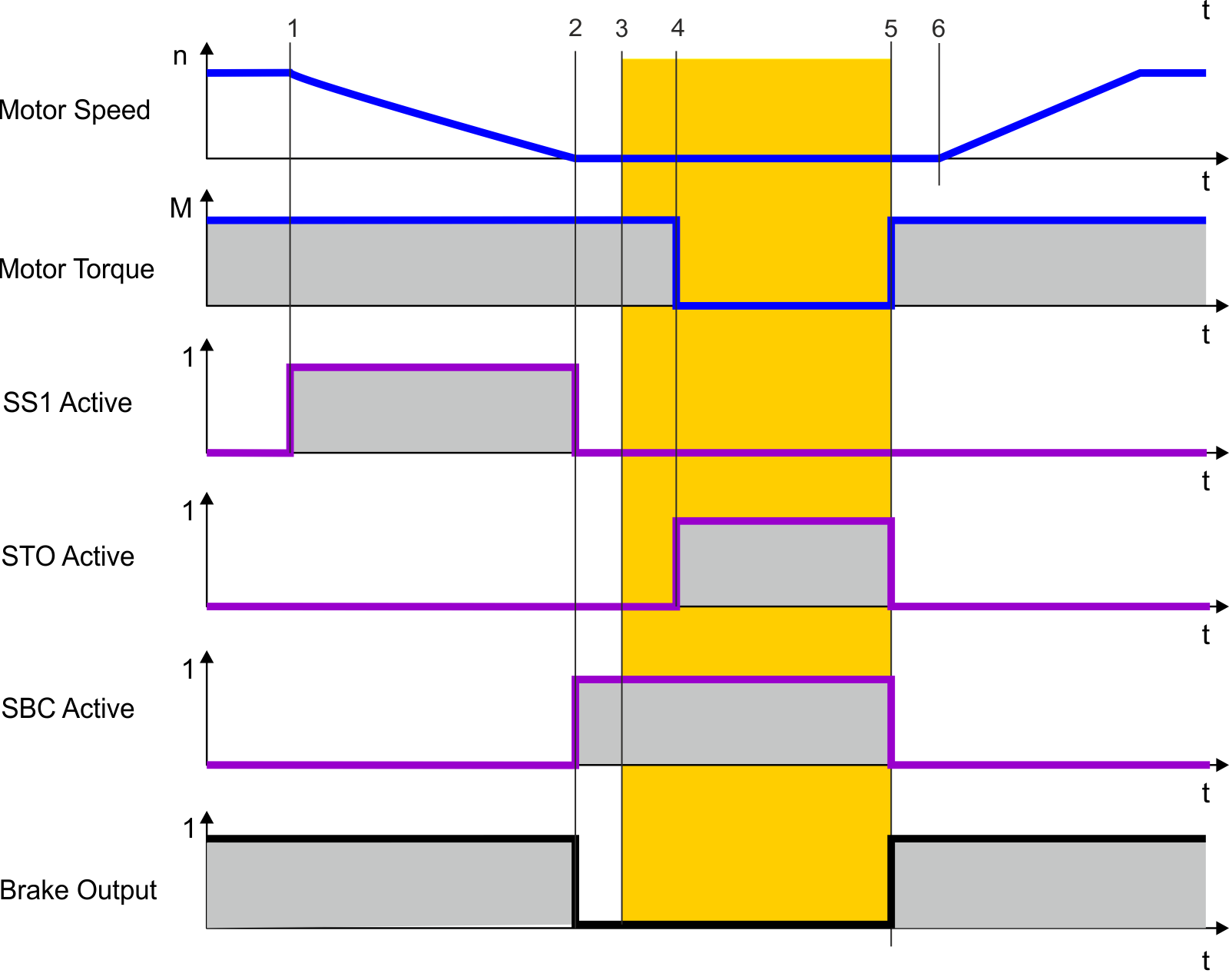
Timing: SS1 followed by SBC without SDB
Process:
- STO is requested.
- The brake output is deactivated.
- The system activates STO after the configured brake delay elapsed.
|
Timing |
Max. |
Remarks |
|---|---|---|
|
t1 |
|
SS1 activate |
|
t1 to t2 |
configurable |
t_SS1: Time window for deceleration |
|
t2 |
|
SBC activate brake output 0V |
|
t2 to t3 |
see brake datasheet |
Brake engaging |
|
t3 |
|
Brake is applied |
|
t2 to t4 |
configurable |
tSBC: Brake time delay |
|
t4 |
|
STO activate |
|
t5 |
|
STO, SBC deactivate, Brake output 24V |
|
t5 to t6 |
see brake datasheet |
Brake disengaging |
|
t6 |
|
Brake is released |
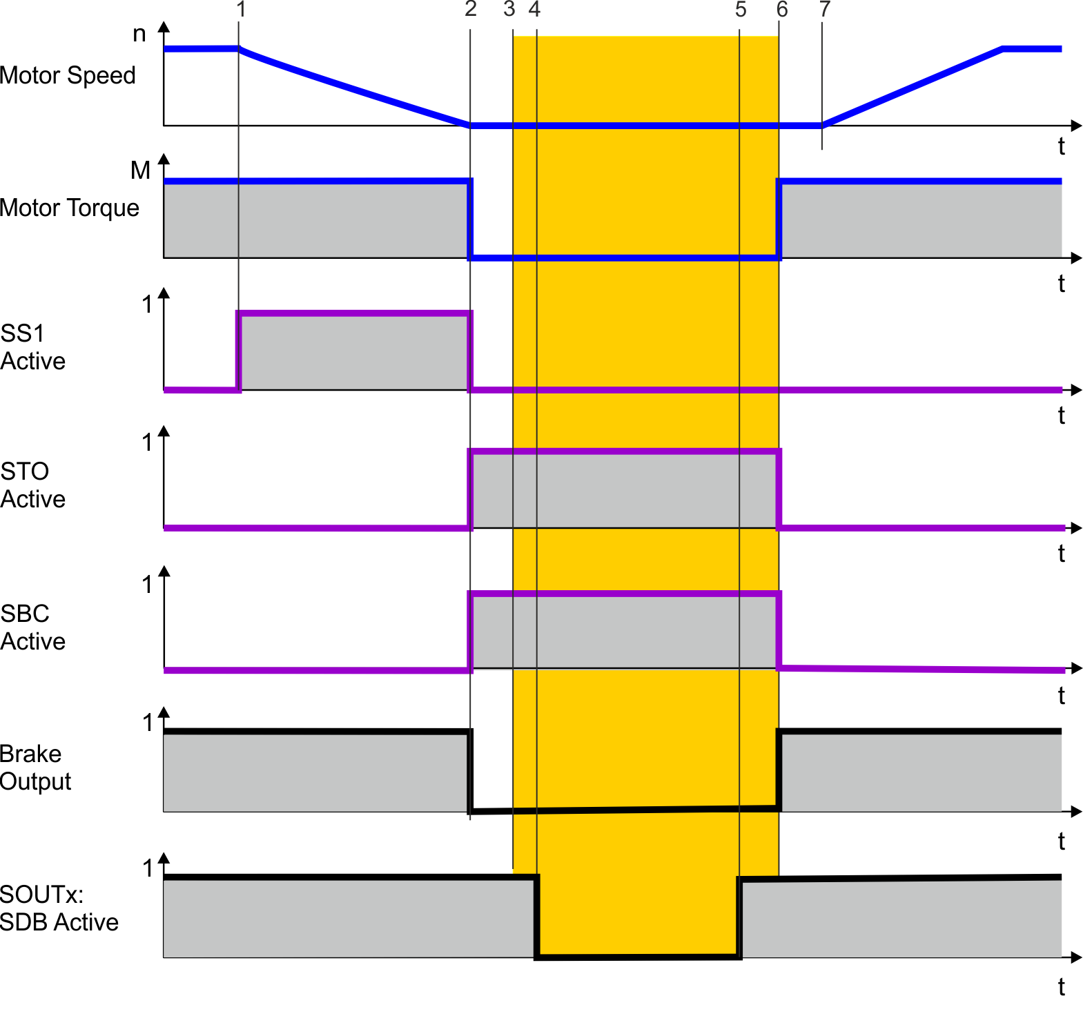
Timing: SS1 followed by SBC with SDB
Process:
- STO is requested.
- The brake output and the output power stage are deactivated simultaneously.
| SMM 1.04 | SMM R_02-07-000 | |||
|---|---|---|---|---|
|
Timing |
Max. |
Remarks |
Max. |
Remarks |
|
t1 |
|
SS1 activate |
|
SS1 activate |
|
t1 to t2 |
configurable |
t_SS1: Time window for deceleration |
configurable |
t_SS1: Time window for deceleration |
|
t2 |
|
SBC activate. Brake output 0V |
|
SBC activate. Brake output 0V |
|
t2 to t3 |
see brake datasheet |
Brake engaging |
see brake datasheet |
Brake engaging |
|
t3 |
|
Brake is applied |
|
Brake is applied |
|
t2 to t4 |
configurable |
tSDB: Delay before switching |
fixed |
Delay of 6ms |
|
t5 |
|
SDB active. SOUTx active |
|
SDB active. SOUTx active |
|
t5 to t6 |
configurable |
tSDB: Delay before switching |
fixed |
Delay of 6ms |
|
t6 |
|
STO and SBC deactivates |
|
STO and SBC deactivates |
|
t6 to t7 |
see brake datasheet |
Brake disengaging |
see brake datasheet |
Brake disengaging |
|
t7 |
|
Brake is released |
Brake is released |
|
Note: tSBC is not used in case SDB is configured.
Setup in WorkBench
Select Safety Parameterization view (see "WorkBench Safety Function Setup"). Choose the axis (1), category (2) and SBC function (3). The instance number (4) is not applicable for SBC.
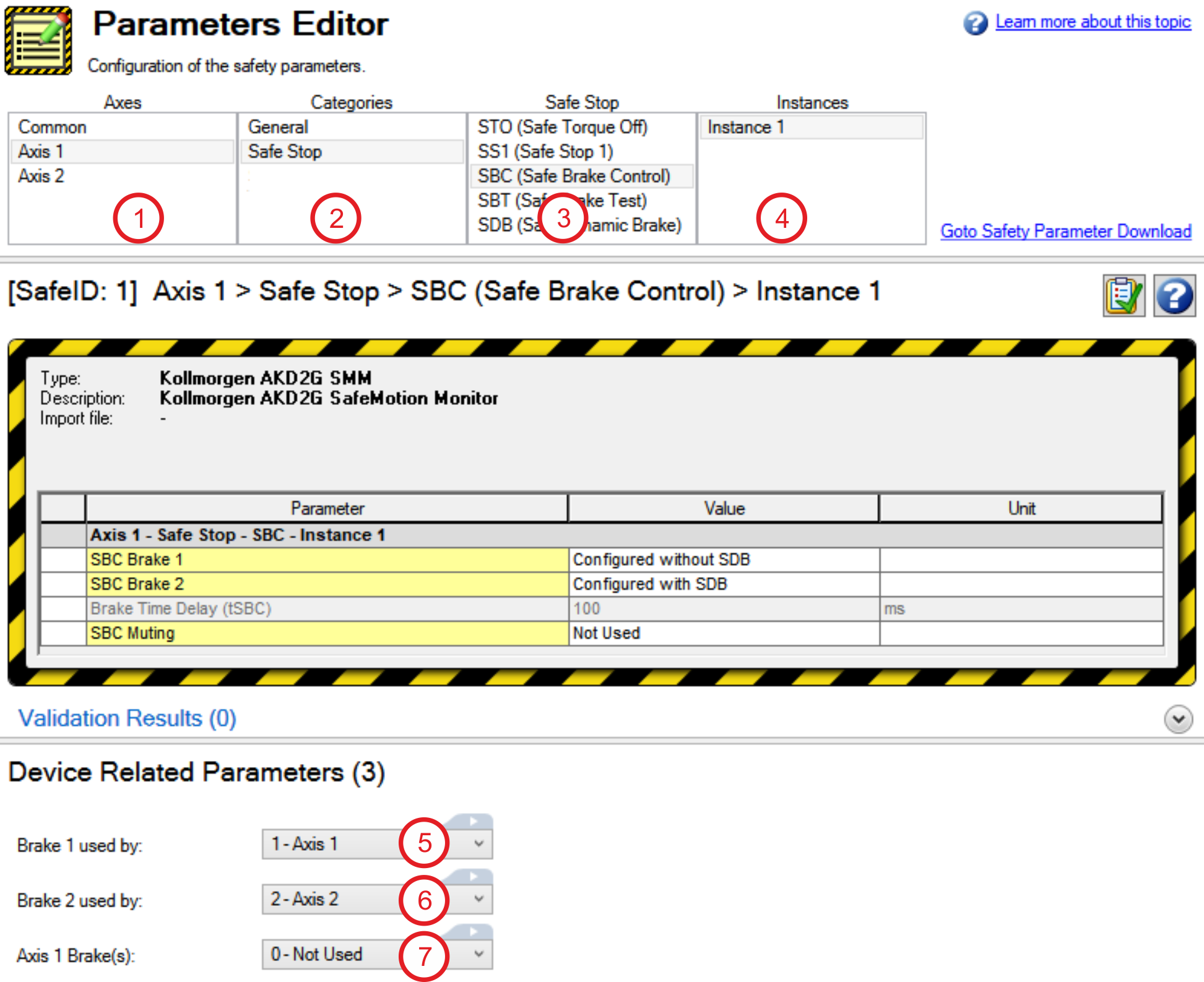
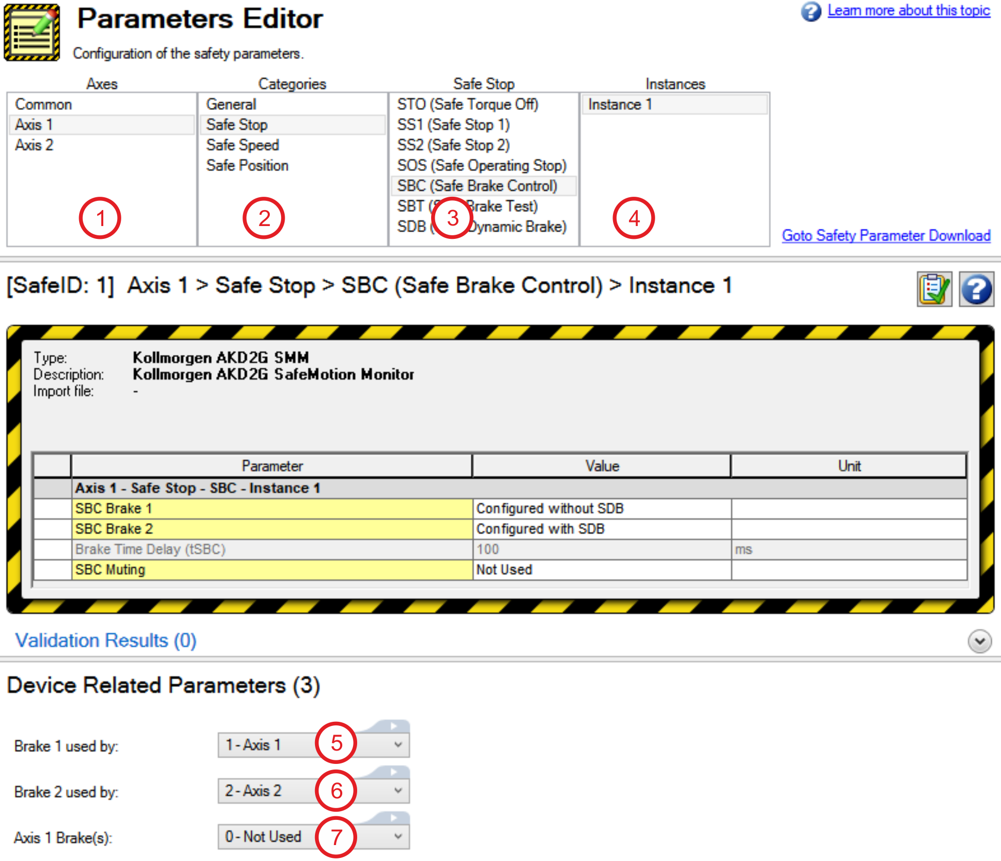
Each brake needs to be assigned to its controlling axis with the device related parameters:
Assigne the axis for Brake1 (5), assigne the axis for Brake2 (6).
(7) indicates whether the drive has detected a brake for the corresponding axis.
|
|
The device related parameter settings are not safe. Changing the configuration in this view will affect the device related parameters. If the configuration collides with the safe settings, warning 9007 will be issued when the axis is disabled. Enabling the affected axis will be prohibited in this case. |
On single axis drives, axis 1 can be configured to control brake 1 and 2 with SBC. For dual axis drives, the brake configuration must be considered:
|
Assignment |
Axis# |
Brake1 |
Brake2 |
Comment |
|---|---|---|---|---|
|
Example 1 |
Axis1 |
SBC |
SBC |
If both brakes are assigned to axis1, axis2 cannot control any of those two brakes. |
|
Axis2 |
- |
- |
||
|
Example 2 |
Axis1 |
SBC |
- |
If axis1 controls brake1 with SBC, axis2 can control brake2 with SBC. |
|
Axis2 |
- |
SBC |
||
|
Example 3 |
Axis1 |
- |
- |
If both brakes are assigned to axis2, only brake2 can be controlled with SBC. Brake1 will be controlled, but not safe (no SBC). |
|
Axis2 |
no SBC |
SBC |
Fault Reaction / Failure Messages
It is not possible to detect a malfunctioning brake through SBC. Therefore diagnosis with SBT is necessary in regular time intervals (see (➜ # 1, SBT (Safe Brake Test))).
A disconnected brake or an open circuit on the brake connectors (X1, X2 or X4) will result in an I/O failure causing SS1_1 (fault reaction) to be triggered followed by STO.
An I/O failure warning is issued when the AKD2G is disabled.
A fault will be issued when the AKD2G is enabled and AXIS#.SAFE.STO.REPORTFAULT is set to 1.
Safety State / Status Signals
See Fault reaction/Failure messages in chapter (➜ # 1, SBT (Safe Brake Test))
Safety Properties
Refer to (➜ # 1, Safety Properties Overview).


