


SS2 (Safe Stop 2)
Description of SS2 with deceleration monitoring enabled for drive option Functional Safety 3.
Description
SS2, when activated, monitors the controlled stop on a given axis until it is ready to activate SOS.
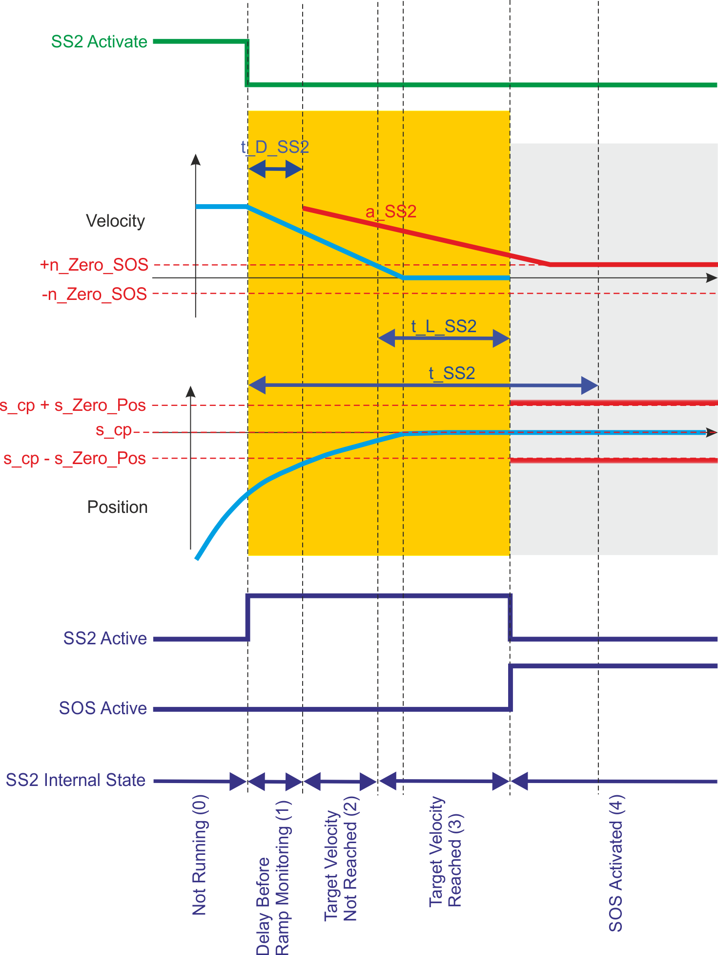
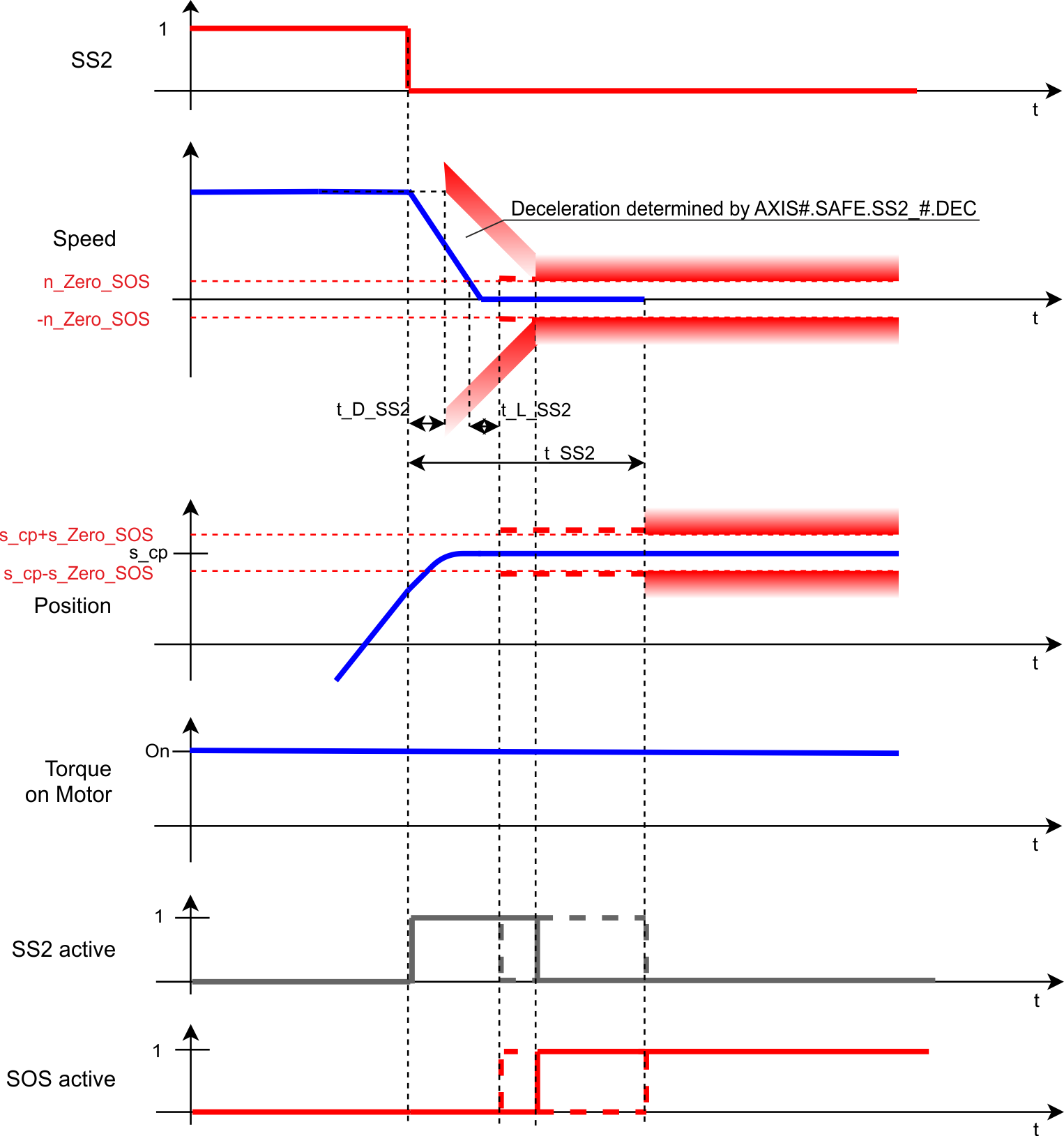
The SS2 function monitors the velocity of the controlled stop. If the velocity stays in the range (n_Zero_SOS) within the time (t_L_SS2) SOS activates in advance. In any case, SOS activates as soon as the timer (t_SS2) elapsed.
Optionally, the ramp of the controlled stop can be monitored. The parameter a_SS2 defines the deceleration limit that the axis cannot pass. The parameter t_D_SS2 is used to delay the start of the deceleration monitoring after the SS2 function activated.
|
|
SMM 1.04 |
SMM R_02-07-000/SMM R_03-00-003 |
|---|---|---|
|
|
|
|

Number of Instances
Two instances per axis.
Function Input / Output Variables
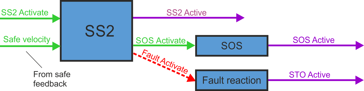
Inputs
- SS2 Activate can be triggered by any of the following:
- FSoE
- safe digital inputs (must be mapped)
- other safety functions as fault reaction*.
- Safe velocity: velocity signal from safe feedback
Outputs
- SS2 Active: logical status of the SS2 function
- Fault Activate: activate fault reaction
*SS2 instance 1 can be configured as fault reaction for: SSR, SDI, SLA, SAR, SLI, SLP and SLS.
Activation
|
Activation by FSoE |
|
|
Activation by safe digital inputs |
|
Safety Properties
Refer to (➜ # 1, Safety Properties Overview).
Timing
Note:
- SS2 is fully completed after activation until SOS is activated, even if the request (SS2_Activate) is reset in between.
The position s_cp is defined when the monitoring of the SOS function begins. It is used to compute the range of allowed position values that the axis can take while the position monitoring is activated. The range is computed by adding or substracting s_Zero_SOS to/from the parameter s_cp.
Related Parameters
Safety parameters
|
Name |
Variables |
Default |
Parameter |
|---|---|---|---|
|
Function Activation |
- |
0 (Never active) |
|
|
Safe Input |
- |
0 (Not used) |
|
|
FSoE |
- |
0 (Not used) |
|
|
Time To SOS |
t_SS2 |
2 ms |
|
|
Time For Velocity Zero |
t_L_SS2 |
1 ms |
|
|
Deceleration Monitoring |
- |
0 (Disabled) |
|
|
Deceleration Limit |
a_SS2 |
0 (Dec user units) |
|
|
Time Delay Deceleration Monitoring |
t_D_SS2 |
1 ms |
|
|
Fault Reaction |
- |
1 (STO) |
Diagnostic parameters
| Name |
Variables |
Default |
Parameter |
|---|---|---|---|
|
Function Active Status |
- |
- |
|
|
Function Internal Status |
- |
- |
Device parameters
|
Name |
Variables |
Default |
Parameter |
|---|---|---|---|
|
Deceleration Mode |
- |
0 (Drive driven) |
|
|
Deceleration Ramp |
- |
9999.946 rpm/s |
State diagram
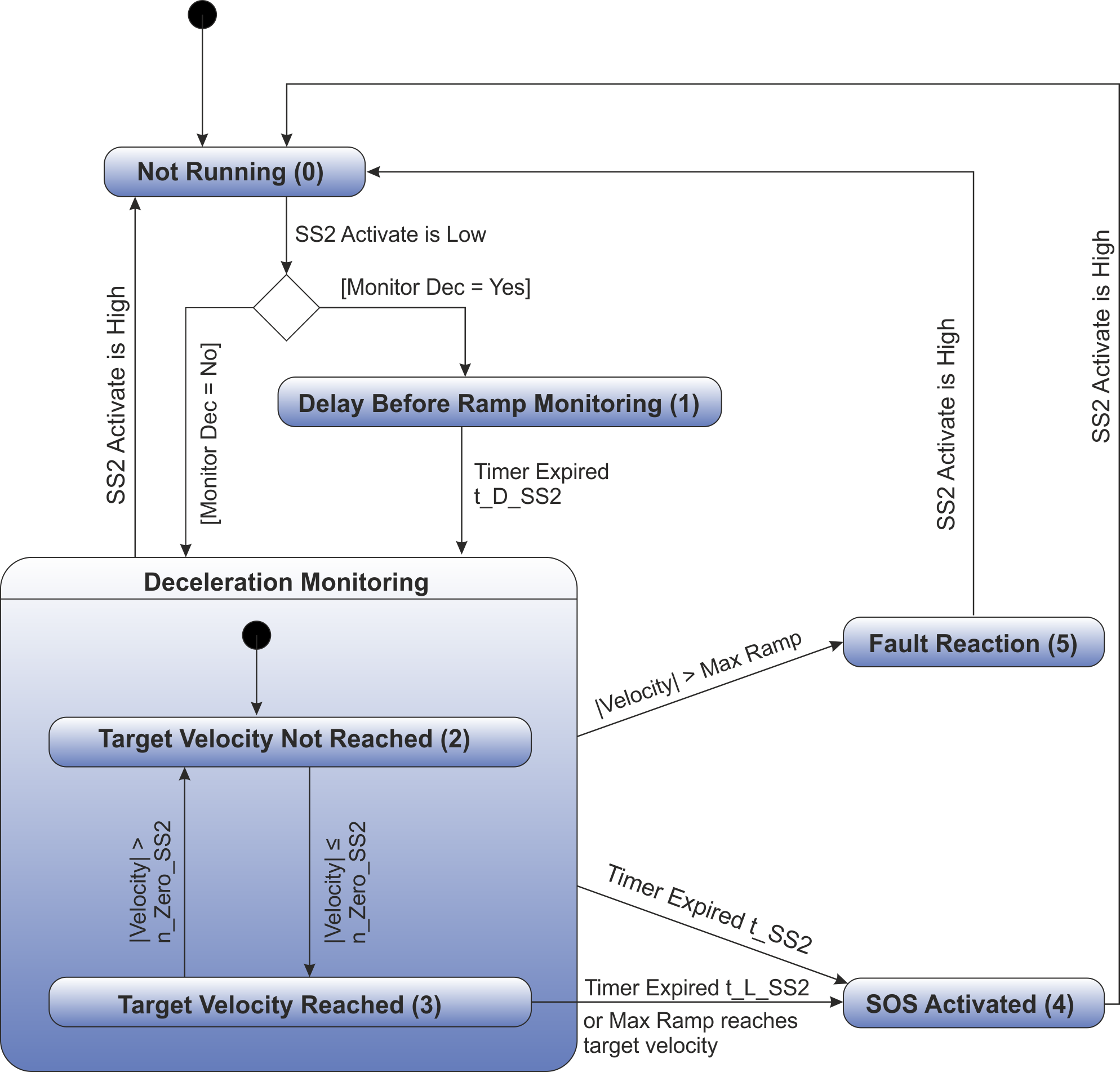
SS2 is active when its internal state is in the composite state "Deceleration Monitoring" or "Delay Before Ramp Monitoring (1)".
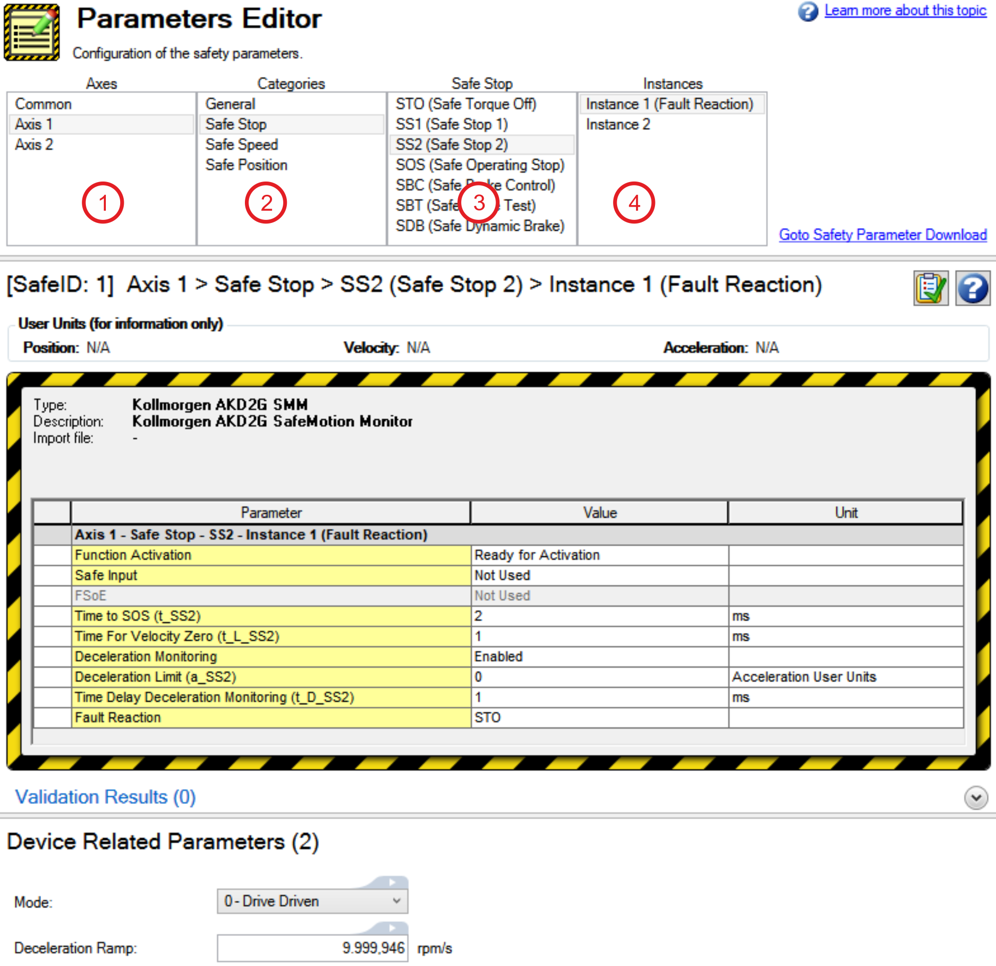
Setup in WorkBench
Select the drive and open the Safety Parameterization view (see "Parameters Editor").
|
|
Fault Reaction / Failure Messages
SS2 has a configurable fault reaction. STO is used by default but can be replaced by SS1 Instance 1. When the fault reaction is activated, the internal state (AXIS#.SAFE.SS2_#.INTERNALSTATE) is set to failed state (5).
SS2 Instance 1 can be configured as the fault reaction for other safety functions. Functions which support this feature are SSR, SDI, SLA, SAR, SLI, SLP and SLS.
Safety State / Status Signals
The signal AXIS#.SAFE.SS2_#.ACTIVE can be monitored by safe digital outputs with OSSD pulses (see "OSSD"). The status signal must be mapped to the safe digital output. Two outputs can be combined to a dual channel output. For parameter description refer to Functional Safety Parameter Reference.


