


Part 10: Diagnostics and Status
The following steps will allow the user to experiment and get familiar with triggering AOIs and the basic functionality the AOIs provide. Axis 1 (Rotary) will be used to demonstrate.
Diagnostics and Status
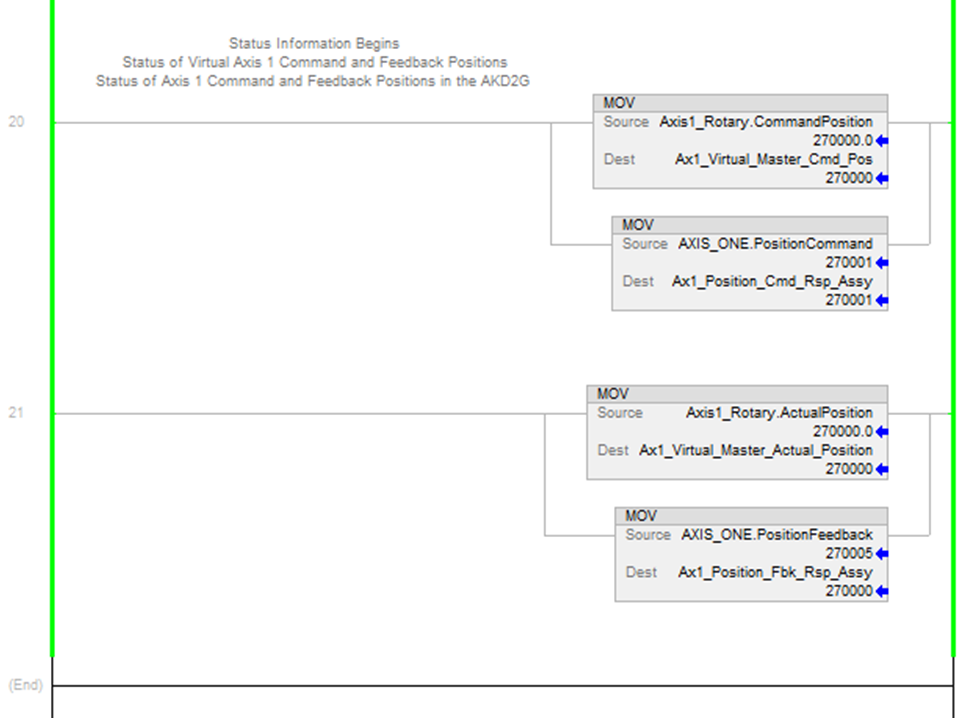
In the Sample project there are several features demonstrated for diagnostics and status. These can be viewed in the Axis1_Routine under MainProgram.
| Axis |
Source Tag |
Source Tag Description |
Destination Tag for viewing in the ladder |
|---|---|---|---|
| Virtual Axis |
Axis1_Rotary.CommandPosition |
Command Position from the Virtual Axis in the Motion Group named Axis1_Rotary |
Ax1_Virtual_Master_Cmd_Pos |
| AKD2G Axis |
AXIS_ONE.PositionCommand |
Command Position reported by the AKD2G’s CIP Sync response assembly for Axis 1. |
Ax1_Position_Cmd_Rsp_Assy |
| Virtual Axis |
Axis1_Rotary.ActualPosition |
Actual Position from the Virtual Axis in the Motion Group named Axis1_Rotary |
Ax1_Virtual_Master_Actual_Position |
| AKD2G Axis |
AXIS_ONE.PositionFeedback |
Command Position reported by the AKD2G’s CIP Sync response assembly for Axis 1. |
Ax1_Position_Fbk_Rsp_Assy |
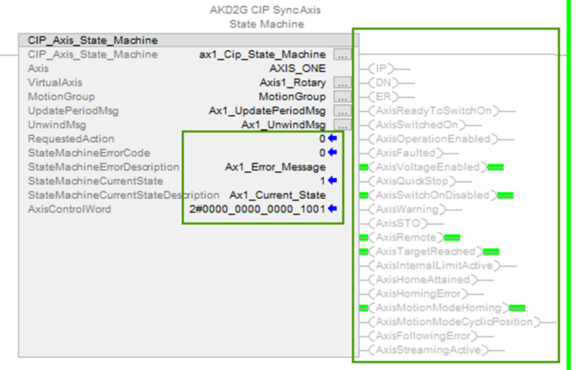
The CIP_Axis_State_Machine AOI for each axis also reports other diagnostics including:
-
Requested Action
-
State Machine Error Code
-
State Machine Error Description
-
State Machine Current State
-
State Machine Current State Description
-
Axis Control Word (shown as binary bits)
-
.IP, .DN, .ER status of the AOI
-
Axis Status bits (shown as outputs of the AOI)
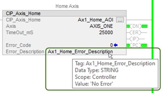
Each AOI for commands such as Enable, Disable, Home, etc. have an Error Code and an Error_Description which can be viewed when the mouse cursor is hovered over the tag for Error_Description.
Testing Axis 2
If the user is bench testing an AKD2G-SPI drive with a second axis, the Sample project assumes the second axis is setup as a linear axis using target positions in mm (millimeters). Repeat the procedure using the same steps used for Axis 1.


