Ex. 3: CIP Sync - Touch Probes - Simple Example
In this example, one touch probe and a rising edge will be used to capture the position, timestamp, and if desired, the count. This example will assume the touch probe has to be rearmed after a capture to generate a new capture (versus a continuous trigger). Axis 1 will be assumed and the default AXIS#.EIP.TP.SOURCE1 is DIN1.
| Touch probe 1 | Touch probe 2 | ||
|---|---|---|---|
| Keyword | Description | Keyword | Description |
|
Touch probe 1 control byte |
Touch probe 2 control byte |
||
|
Touch probe 1 status byte |
Touch probe 2 status byte |
||
|
Touch probe 1 position positive value |
Touch probe 2 position positive value |
||
|
Touch probe 1 position negative value |
Touch probe 2 position negative value |
||
|
Touch probe 1 source |
Touch probe 2 source |
||
|
Touch probe 1 timestamp positive value |
Touch probe 2 timestamp positive value |
||
|
Touch probe 1 negative value |
Touch probe 2 timestamp negative value |
||
|
Touch probe 1 positive edge counter |
Touch probe 2 positive edge counter |
||
|
Touch probe 1 negative edge counter |
Touch probe 2 negative edge counter |
||
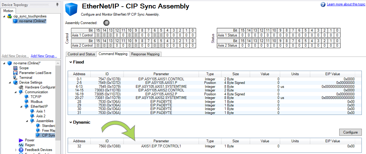
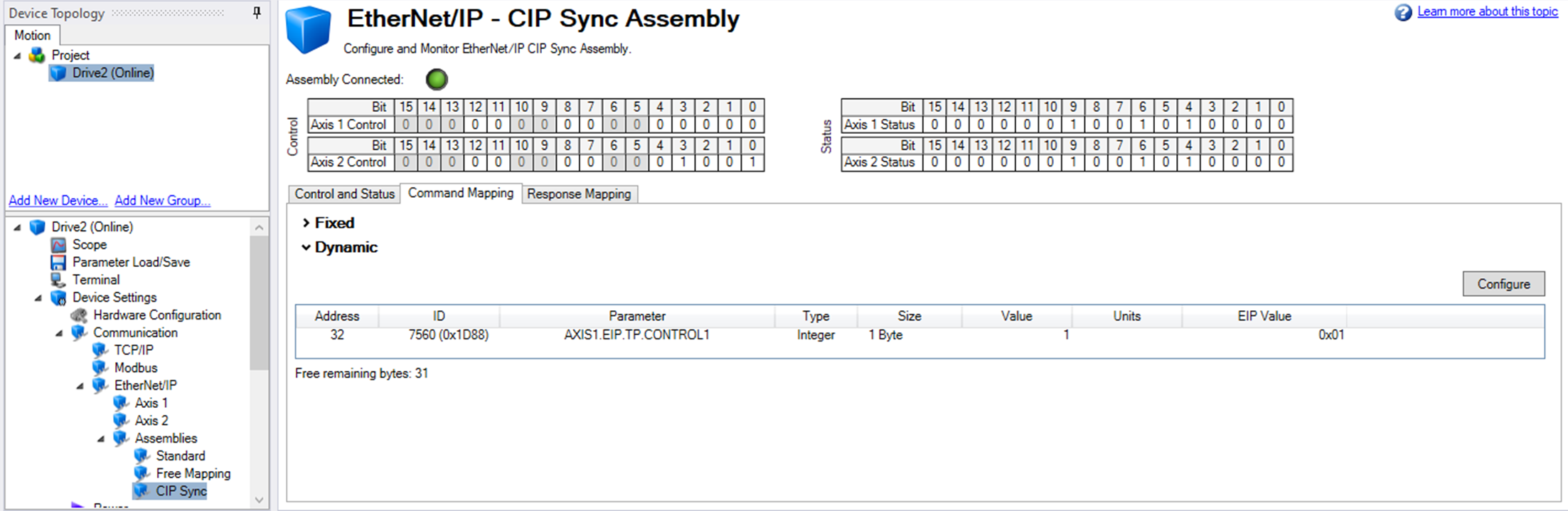
To control the arming and disarming of Touch probe 1, AXIS1.EIP.TP.CONTROL1 is mapped to the Command Mapping region of the CIP Sync Assembly using the WorkBench GUI.
| Keyword | Description |
|---|---|
|
AXIS1.EIP.TP.CONTROL1 |
Modifies and configures the associated axis’ first touch probe control byte. |
The following is mapped to the Response Mapping tab of the CIP Sync Assembly.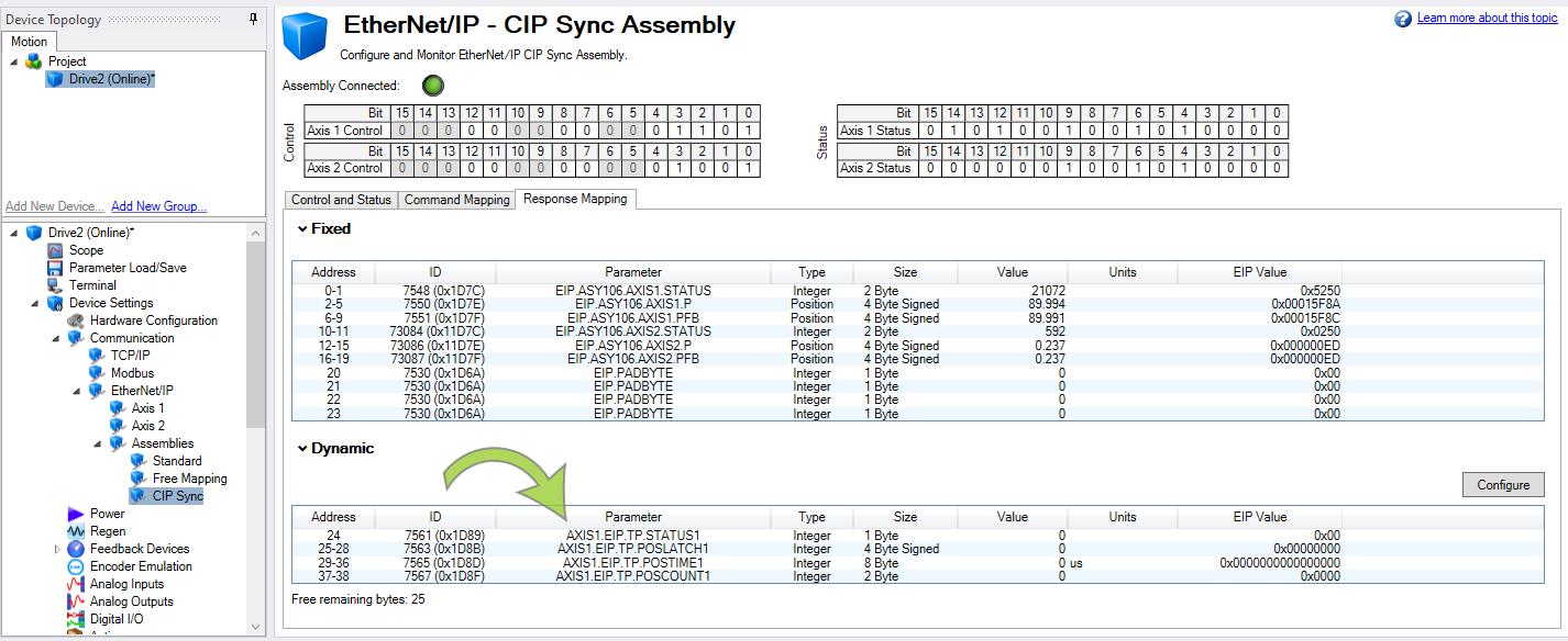
| Keyword | Description |
|---|---|
|
AXIS1.EIP.TP.STATUS1 |
Monitors the status of Touch probe 1 on Axis 1 |
|
AXIS1.EIP.TP.POSLATCH1 |
Monitors and displays the last captured positive latched position on Touch probe 1, Axis 1 |
|
AXIS1.EIP.TP.POSTIME1 |
Monitors and displays the last captured timestamp on Touch probe 1, Axis 1 |
|
AXIS1.EIP.TP.POSCOUNT1 |
Monitors and displays the total running count of the capture even on Touch probe 1, Axis 1 |
Reference the DynamicMap array elements chart in the drop-down below to determine the DynamicMap array elements associated with the parameters.
The following table lists the Dynamic Map Array Elements (1 Byte) and their corresponding Command or Response Byte and WorkBench Address.
| DynamicMap Array Element | Command Byte and WorkBench Address |
DynamicMap Array Element | Response Byte and WorkBench Address |
|---|---|---|---|
|
Name.Output.Data[0] |
32 |
Name.Input.Data[0] |
24 |
|
Name.Output.Data[1] |
33 |
Name.Input.Data[1] |
25 |
|
Name.Output.Data[2] |
34 |
Name.Input.Data[2] |
26 |
|
Name.Output.Data[3] |
35 |
Name.Input.Data[3] |
27 |
|
Name.Output.Data[4] |
36 |
Name.Input.Data[4] |
28 |
|
Name.Output.Data[5] |
37 |
Name.Input.Data[5] |
29 |
|
Name.Output.Data[6] |
38 |
Name.Input.Data[6] |
30 |
|
Name.Output.Data[7] |
39 |
Name.Input.Data[7] |
31 |
|
Name.Output.Data[8] |
40 |
Name.Input.Data[8] |
32 |
|
Name.Output.Data[9] |
41 |
Name.Input.Data[9] |
33 |
|
Name.Output.Data[10] |
42 |
Name.Input.Data[10] |
34 |
|
Name.Output.Data[11] |
43 |
Name.Input.Data[11] |
35 |
|
Name.Output.Data[12] |
44 |
Name.Input.Data[12] |
36 |
|
Name.Output.Data[13] |
45 |
Name.Input.Data[13] |
37 |
|
Name.Output.Data[14] |
46 |
Name.Input.Data[14] |
38 |
|
Name.Output.Data[15] |
47 |
Name.Input.Data[15] |
39 |
|
Name.Output.Data[16] |
48 |
Name.Input.Data[16] |
40 |
|
Name.Output.Data[17] |
49 |
Name.Input.Data[17] |
41 |
|
Name.Output.Data[18] |
50 |
Name.Input.Data[18] |
42 |
|
Name.Output.Data[19] |
51 |
Name.Input.Data[19] |
43 |
|
Name.Output.Data[20] |
52 |
Name.Input.Data[20] |
44 |
|
Name.Output.Data[21] |
53 |
Name.Input.Data[21] |
45 |
|
Name.Output.Data[22] |
54 |
Name.Input.Data[22] |
46 |
|
Name.Output.Data[23] |
55 |
Name.Input.Data[23] |
47 |
|
Name.Output.Data[24] |
56 |
Name.Input.Data[24] |
48 |
|
Name.Output.Data[25] |
57 |
Name.Input.Data[25] |
49 |
|
Name.Output.Data[26] |
58 |
Name.Input.Data[26] |
50 |
|
Name.Output.Data[27] |
59 |
Name.Input.Data[27] |
51 |
|
Name.Output.Data[28] |
60 |
Name.Input.Data[28] |
52 |
|
Name.Output.Data[29] |
61 |
Name.Input.Data[29] |
53 |
|
Name.Output.Data[30] |
62 |
Name.Input.Data[30] |
54 |
|
Name.Output.Data[31] |
63 |
Name.Input.Data[31] |
55 |
|
|
|
Name.Input.Data[32] |
56 |
|
|
|
Name.Input.Data[33] |
57 |
|
|
|
Name.Input.Data[34] |
58 |
|
|
|
Name.Input.Data[35] |
59 |
|
|
|
Name.Input.Data[36] |
60 |
|
|
|
Name.Input.Data[37] |
61 |
|
|
|
Name.Input.Data[38] |
62 |
|
|
|
Name.Input.Data[39] |
63 |
For this example the following is true:
| Mapped Parameter | Data Type | WorkBench Addresses | DynamicMap Array in PLC | Tag Data Type |
|---|---|---|---|---|
|
AXIS1.EIP.TP.CONTROL1 |
1 Byte |
32 |
Name.Output.Data[0] |
SINT |
| Mapped Parameter | Data Type | WorkBench Addresses | DynamicMap Array in PLC | Tag Data Type |
|---|---|---|---|---|
|
AXIS1.EIP.TP.STATUS1 |
1 Byte |
24 |
Name.Input.Data[0] |
SINT |
|
AXIS1.EIP.TP.POSLATCH1 |
4 Byte Signed |
25-28 |
Name.Input.Data[1] to Name.Input.Data[4] |
DINT |
|
AXIS1.EIP.TP.POSTIME1 |
8 Byte |
29-36 |
Name.Input.Data[5] to Name.Input.Data[12] |
LINT |
|
AXIS1.EIP.TP.POSCOUNT1 |
2 Byte |
37-38 |
Name.Input.Data[13] to Name.Input.Data[14] |
INT |
The following sample code was written in the PLC for the example application.
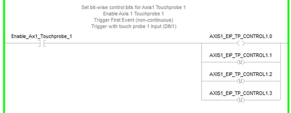
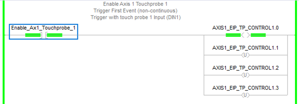
The first rung provides a N.O. contact Enable_Ax1_Touchprobe_1 to enable or disable Touch probe 1 for Axis 1.
-
Bit 0 = Enable/Disable when ON/OFF.
-
Bit 1 = Trigger First Event (non-continuous) when OFF.
-
Bits 2 and 3 when OFF, OFF sets the trigger with touch probe 1 input (DIN1).
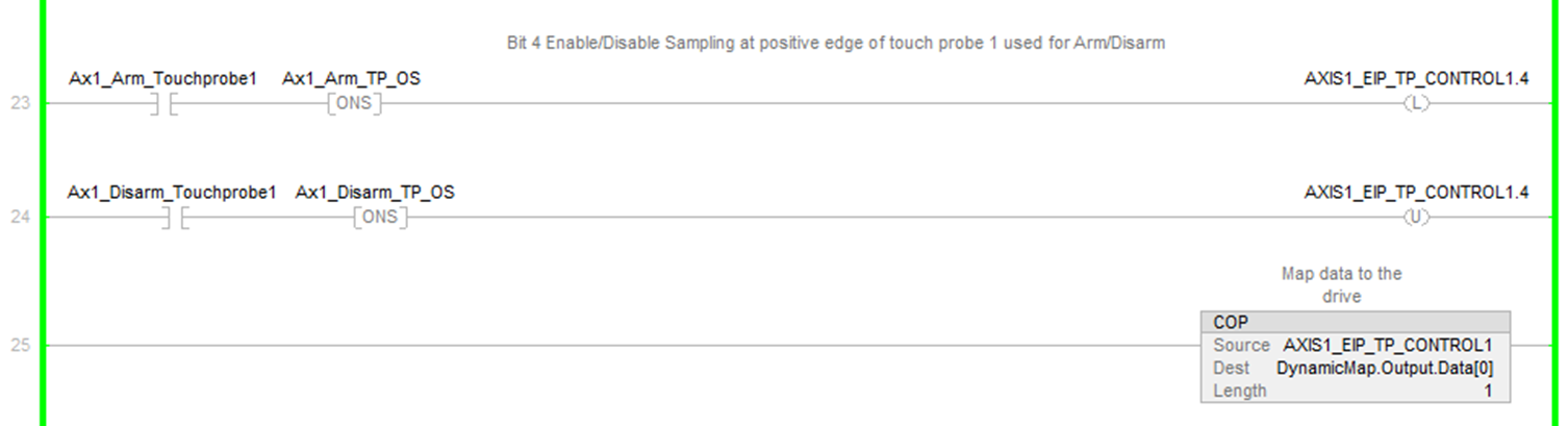
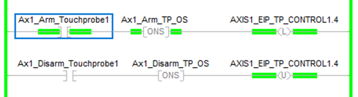
The next two rungs use Bit 4 to arm or disarm the sampling of the positive edge of touch probe 1 for Axis 1.
The rung with the COP instruction sends the PLC data to the dynamically mapped control Byte.
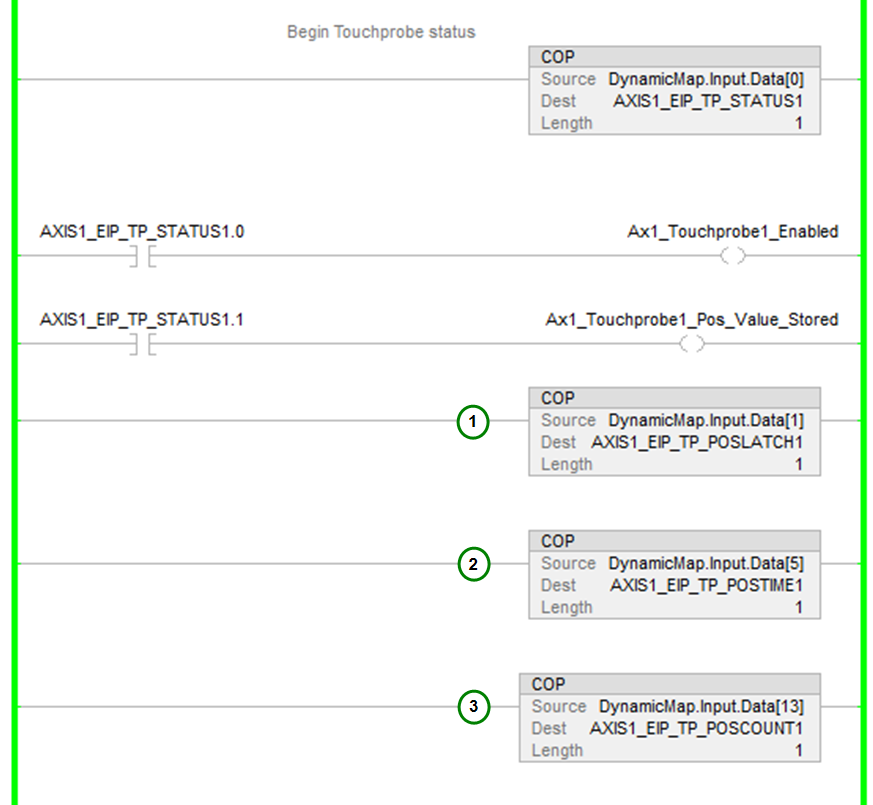
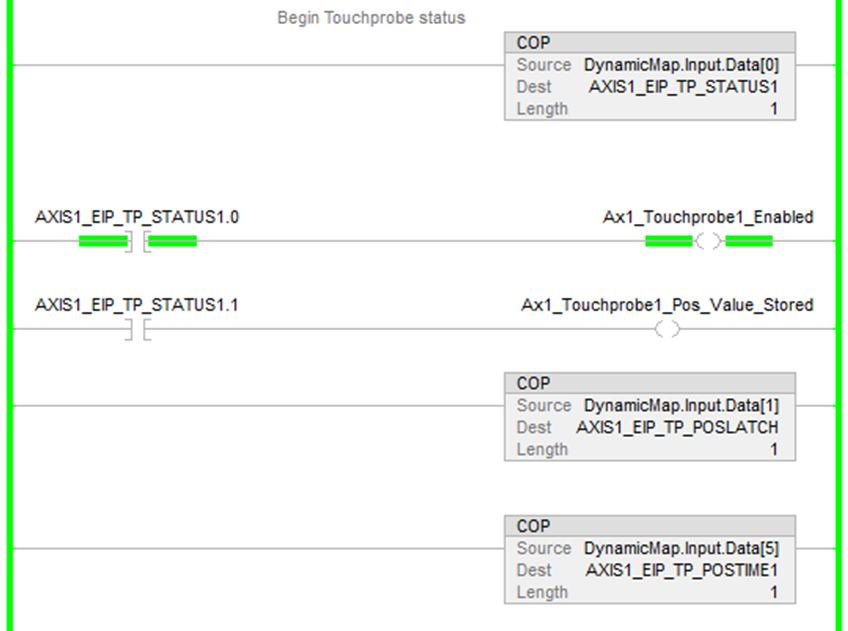
In the following rungs for Touch probe status the dynamically mapped status Byte data is copied into a tag in the PLC.
-
Bit 0 of the tag indicates when the touch probe is enabled or disabled.
-
Bit 1 of the tag indicates when a positive value of touch probe 1 of Axis 1 is stored.
The stored bit behavior is such when the touch probe is armed and DIN1 input triggers the event on positive edge, status bit 1 turns ON indicating a new position capture occurred. When the control Byte disarms the sampling, bit 1 of the status Byte turns OFF. On re-arm and a new rising edge and capture, bit 1 turns ON again.
The next three rungs with COP instructions copy the dynamically mapped data into tags for monitoring in the ladder:
|
|
Demonstration
-
First, enable the touch probe.
The control byte changes to a value of 1 (0x01).
-
Next, arm the touch probe.
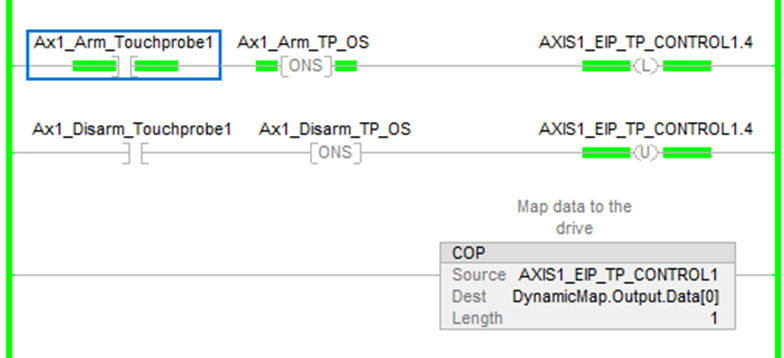
The control byte changes to a value of 17 (0x11).
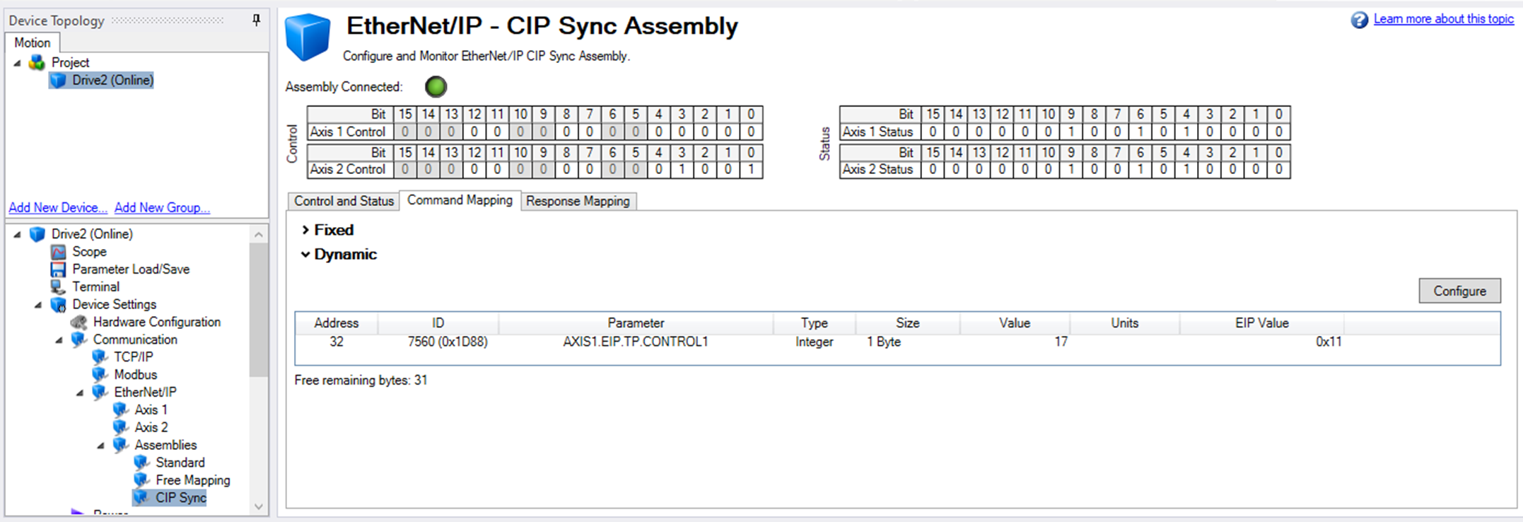
In the Response Mapping tab, the status (AXIS1.EIP.TP.STATUS1) has a value of 1 (0x01). AXIS1.EIP.TP.POSLATCH1 and AXIS1.EIP.TP.POSCOUNT1 both have a value of 0.

The Touch probe status indicates the touch probe is enabled.
On the rising edge of DIN1 (Digital Input 1) the positive value stored coil, Ax1_Touchprobe1_Pos_Value_Stored, turns ON indicating a new touch probe capture occurred. 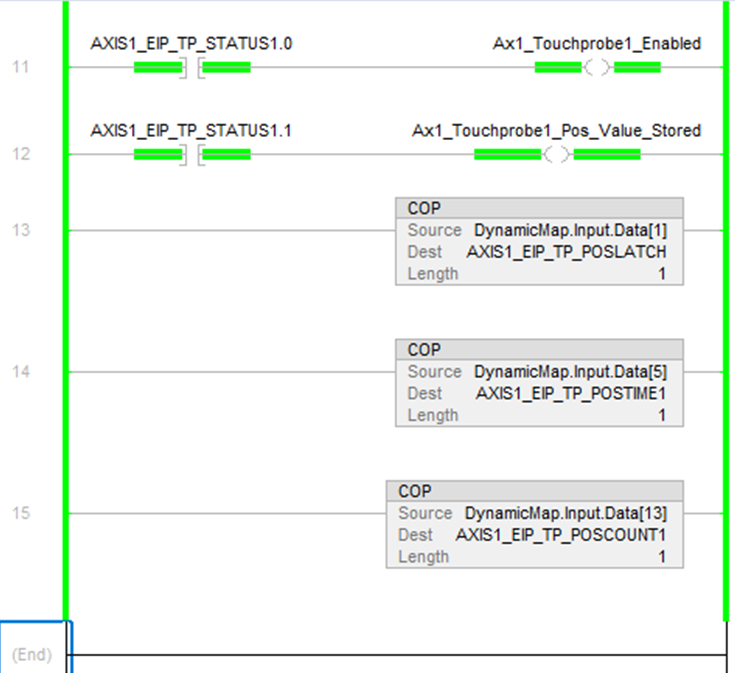
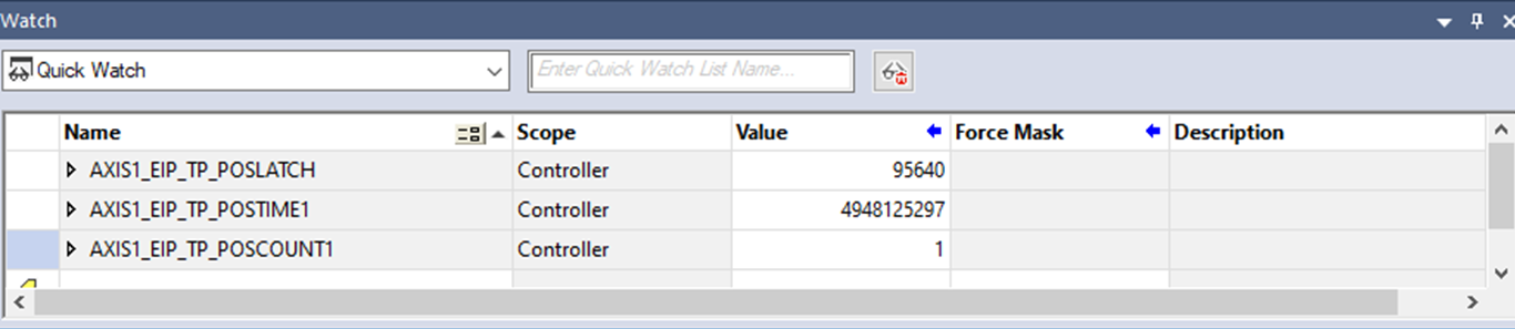
In Studio 5000's Quick Watch window the AXIS1_EIP_TP_POSLATCH1 value is 95640 and the AXIS1_EIP_TP_POSCOUNT1 is 1. The AXIS1_EIP_TP_POSTIME1 is the sync time taken at the time of the Touch probe capture.
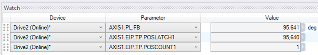
Compare this to the Watch window in WorkBench where the position feedback is 95.641 deg and positive latched position is 95.640. This example assumes the EIP scaling for Axis 1 is setup for Ratio Input = 360000 and Ratio Output = 1 for degrees. See Scaling section for examples.
-
To take another position capture, first disarm the touch probe.
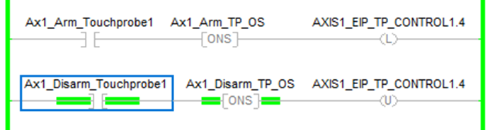
-
Next, rearm the touch probe.
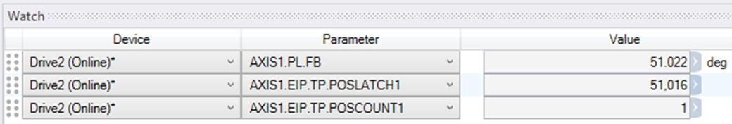
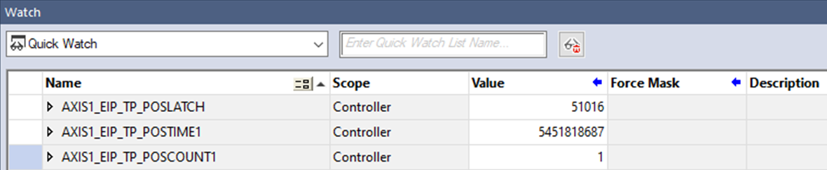
On rising edge of DIN1 the position capture takes place and a new value is stored. The Quick Watch window in Studio 5000 displays AXIS1_EIP_TP_POSLATCH1 with a value of 51016, AXIS1_EIP_TP_POSTIME1 with a value of 5451818687, and AXIS1_EIP_TP_POSCOUNT1 with a value of 1.
WorkBench's Watch window displays AXIS1.PL.FB with a value of 51.1022 deg, AXIS1_EIP_TP_POSLATCH1 with a value of 51.106, and AXIS1_EIP_TP_POSCOUNT1 with a value of 1.