


Resonator (Notch) Filter
| Parameter | Description | Drive Keyword |
|---|---|---|
|
PL.KP |
Position Loop Proportional Gain |
|
|
VL.ARTYPE# |
Anti-Resonace Filter Type |
|
|
VL.ARZF# |
Filter Zero Cutoff Frequency |
|
|
VL.ARZQ# |
Filter Zero Q Value |
|
|
VL.ARPF# |
Filter Pole Frequency |
|
|
VL.ARPQ# |
Filter Pole Q Value |
|
|
VL.KI |
Velocity Loop Integral Gain |
|
|
VL.KP |
Velocity Loop Proportional Gain |
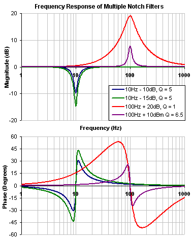
A notch filter changes gain at a specific frequency. To define a notch filter the following must be specified.
- The frequency at which the gain change occurs (Frequency (Hz))
- How wide of a frequency range the cut occurs (Q)
- How much the gain changes (Notch Depth (dB)).
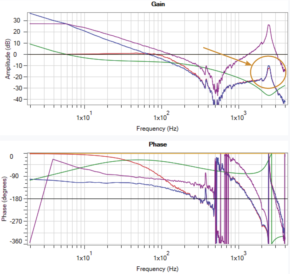
Review: The Controller [C] trace shows the frequency response of VL.KP, VL.KI, PL.KP, AR Filters 1 & 2
Note: Here VL.KP is set to 1.0 so that the gain of the system is at 0dB
A resonator filter is a specialized filter. It has three parameters:
-
Center Frequency
-
Gain
-
Bandwidth (Q)
It is not referred to as a Notch, because Notch filters can only subtract gain, the Resonator can add gain too!
Common Resonator Uses:
-
Notch out a single high gain resonance
-
Reduce/Increase gain over a range of frequencies
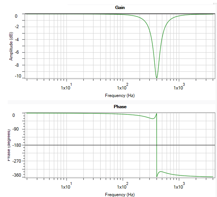
Shown to the side is a 400Hz -10dB Resonator with Q = 1.0
When tuning a Resonator, care must be taken to fine tune all three parameters
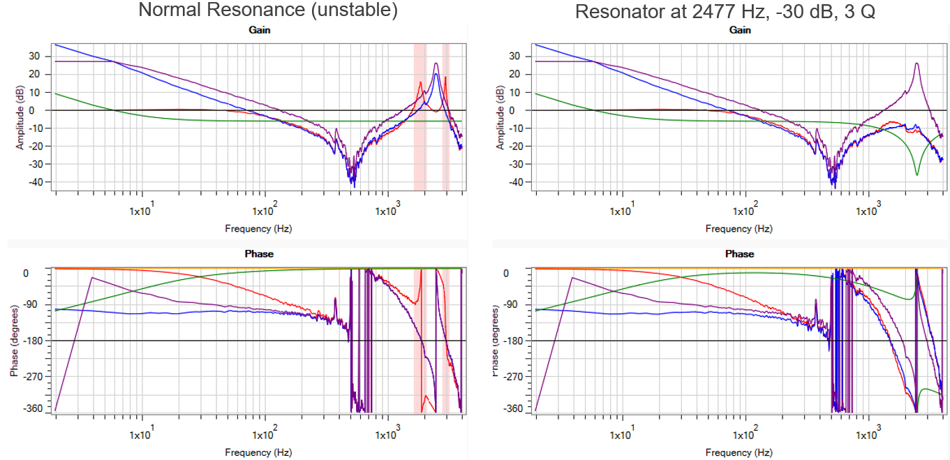
If one parameter is off, results can be drastically different!
|
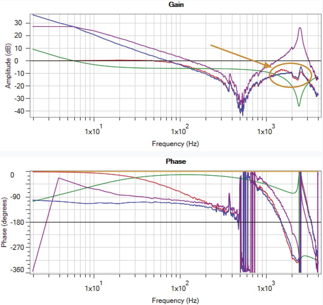
Here the resonator has the same gain and bandwidth, but the frequency has been set to 2400 Hz instead of 2477 Hz.
The Frequency is close, but notice the open & closed loop gain are higher than in the well tuned resonator. |
Resonator at 2400 Hz, -30 dB, 3 Q
|
|
Here the resonator has the same gain and frequency, but the bandwidth has been set to 0.5 instead of 3.0
The Bandwidth is close, but notice the open & closed loop gain are higher than in the well tuned resonator |
Resonator at 2477 Hz, -30 dB, 0.5 Q
|
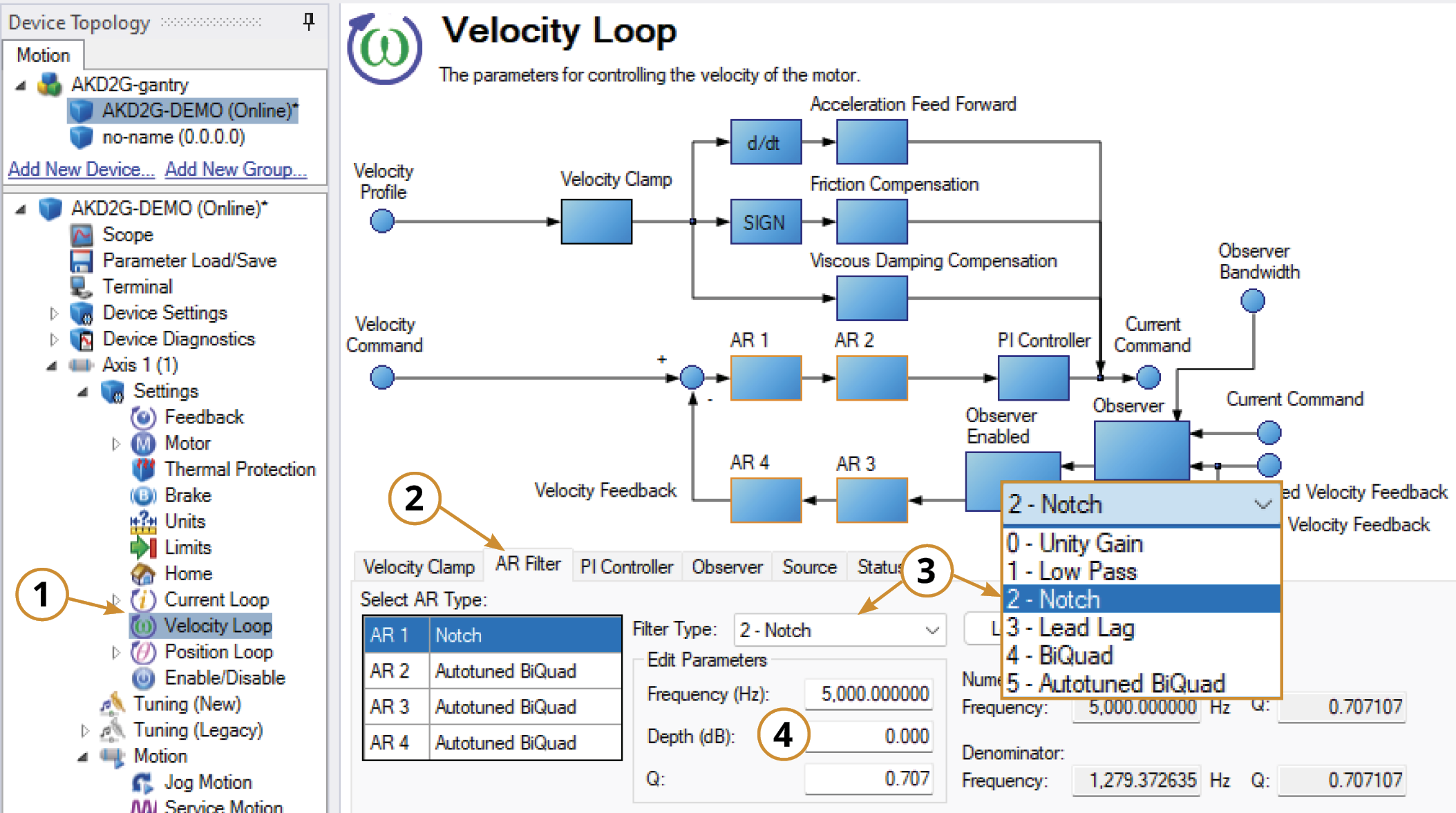
Adjusting Resonator (Notch) in the Velocity Loop
To specify a notch filter, you must specify the Frequency (Hz), Depth (dB) and Width (Q) of the notch. To do this, see the following example by clicking on the Velocity Loop:
-
Open the Velocity Loop pane.
-
Open the AR Filter tab and select the AR filter that will function as Notch.
-
Select 2 - Notch as the Filter Type.
-
Set the desired Frequency, Depth and Q.
Adjusting Resonator (Notch) Using the Manual Tuning Simulator
Within the Velocity Loop section of the Simulation pane, the filter type and values can be entered for AR filters 1-4.
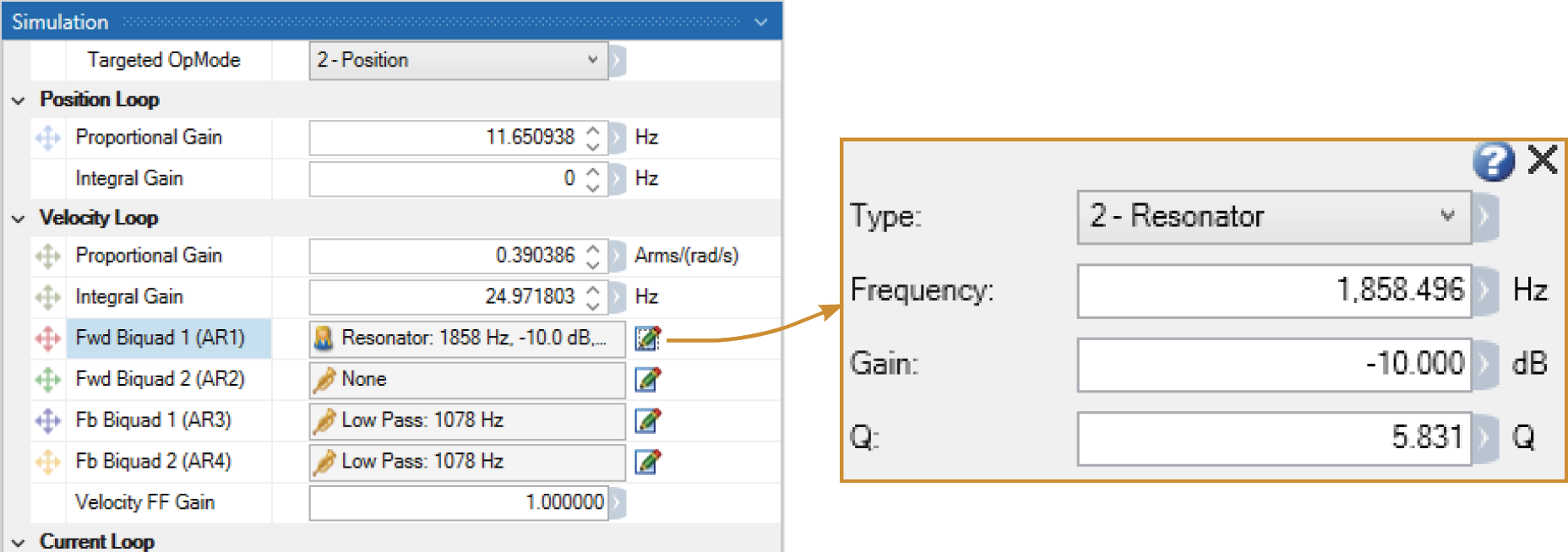
Once the filter type is set to Resonator (Notch), the Bode Plot Drag+Drop tool may be used to visually adjust the values.
After setting the values within the Simulation pane or using the Drag+Drop sliders, the settings must be written to drive to take effect.


